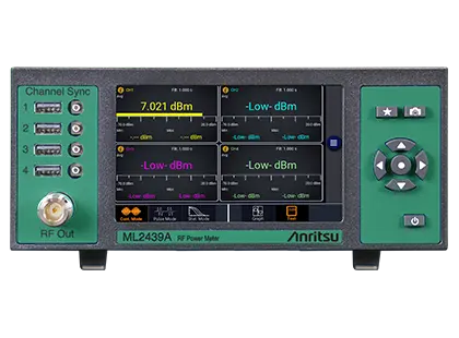
ML2439A Benchtop Power Meter for Anritsu USB Power Sensors, 10 MHz to 50 GHz
Benchtop power meter with 2 or 4 channels for Anritsu USB power sensors, measuring peak, average and RMS power from 10 MHz to 50 GHz.
- Frequency Range
- 10 MHz to 50 GHz (sensor dependent)
- Input Level Range
- -60 dBm to +20 dBm (sensor dependent)
- Channels
- 2 CH Standard, 4 CH with Option -0004
- Sensors
- MA2444xA, MA243xxA, MA242xxA and MA241xxA
Overview
The Anritsu ML2439A is a benchtop power meter that takes input from Anritsu USB power sensors and processes and displays their measurements simultaneously. It has 2 channels as standard, and Option ML2439A-0004 brings it to 4. It works with the MA244xxA peak power sensors, the MA243xxA CW sensors and the MA242xxA and MA241xxA true RMS sensors. The MA24103A, MA24105A and MA24106A are not supported.
Measurements are set up from the front panel with a 5-inch multi-touch display and a keypad. The front panel also has a 50 MHz test source output for checking that sensors work. For remote operation, the instrument offers LAN (Ethernet) and optional GPIB interfaces and supports SCPI commands.
Measurement modes
In Continuous mode, the meter shows average, maximum and minimum signal power as a graph or as numbers. In Pulse mode, it plots pulse amplitude against time and calculates 16 pulse parameters automatically. In Statistical mode, it plots the Complementary Cumulative Distribution Function (CCDF), which shows how often a given crest factor occurs in signals such as 5G, 4G/LTE and Wi-Fi.
Sensor capability
With the MA244xxA USB peak power sensors, which have 195 MHz video bandwidth, the ML2439A can measure very narrow pulse-modulated signals and wideband periodic modulated signals. Multi-channel measurements with these sensors are synchronous. With the MA243xxA CW sensors and the MA241xxA and MA242xxA true RMS sensors, it measures RMS and CW power. The USB sensors can also be disconnected and used on their own as standalone instruments.
Key Features
- Capture/display/analyze peak and average/RMS power
- Synchronous multi-channel measurements with MA244xxA sensors (up to 4 channels)
- Frequency range: 10 MHz to 50 GHz (sensor dependent)
- Video bandwidth: 195 MHz for periodic signals
- Min rise time: < 3 ns
- 100,000 measurements per second measurement speed
- 100 ps time resolution
- 16 automatic pulse measurements
- Max effective sample rate: 10 GS/s
- Max pulse repetition rate: 50 MHz
- Front panel 5-inch WVGA multi-touch display and keypad
- 50 MHz test source output on the front panel to verify sensor operation
- GPIB and LAN interfaces with SCPI command support
- Optional secure USB drive for additional security
- Sensors can be used as standalone instruments
Specifications
| Frequency Range | 10 MHz to 50 GHz (sensor dependent) |
|---|---|
| Input Level Range | -60 dBm to +20 dBm (sensor dependent) |
| Channels | 2 CH Standard, 4 CH with Option -0004 |
| Sensors |
MA2444xA, MA243xxA, MA242xxA and MA241xxA
Except MA24103A, MA24105A and MA24106A
|
| Display | 5-inch WVGA multi-touch display with intuitive graphical user interface |
| Display Modes | Continuous, Pulse and Statistical (CCDF) |
| Display Format | Graph (Power vs time or CCDF), Text (Numeric Display) |
| Automatic measurements | Pulse, statistical, and markers measurements |
| Weight | 4.8 lbs, 2.2 kg |
| Dimensions (H x W x D) | 3.5 x 8.3 x 11.2 (in), 89 x 211 x 284 (mm) |
| Warranty | 1 year from shipment date |
| Calibration Cycle | Recommended calibration cycle is 12 months |
| Max Video Bandwidth (VBW) | 195 MHz |
|---|---|
| Min Rise Time | < 3 ns |
| Measurement/Acquisition Speed | 100,000 measurements per second |
| Time resolution | 100 ps |
| Automatic Pulse Measurements | 16 |
| Max Effective Sample Rate | 10 GS/s |
| Max Pulse Repetition Rate | 50 MHz |
| Front Panel Test Source | RF OUT, 50 MHz, 0 dBm +/-0.1 dB typical |
|---|---|
| Front Panel USB | 4 USB 2.0 ports, Type A receptacle |
| Front Panel Trigger |
4 SMB(f) trigger ports
Only for MA244xxA Peak Power Sensors
|
| Rear Panel LAN | 10/100 Ethernet RJ 45 modular socket |
| Rear Panel USB | 4 USB 2.0 ports, Type A receptacle |
| Rear Panel Trigger |
4 SMB(f) trigger ports
Only for MA244xxA peak power sensors
|
|
Rear Panel GPIB
ML2439A-0005
|
GPIB Port (Option 0005) |
| Rear Panel Other | HDMI Port, External Trigger Input, Multi-I/O |
| Rated Voltage | 100 to 240 VAC |
|---|---|
| Voltage Range | 90 to 264 VAC |
| Rated Frequency | 50/60 Hz |
| Frequency Range | 47 to 63 Hz |
| Power Consumption |
60 W (70 VA) max, 30 W (35 VA) nominal
Nominal with no external peripheral devices attached
|
| Markers (vertical cursors) | Settable in time relative to the trigger position |
|---|---|
| Marker Independently | Avg, Min and Max Power at a specified time offset |
| Interval Between Markers | Avg, Min and Max Power over the defined interval |
| Markers | Ratio of power values at each marker |
| Pulse Mode | Pulse rise-time, Pulse width, Pulse period, Pulse duty cycle, Pulse peak, Pulse overshoot, Top level power, Edge delay, Pulse fall-time, Pulse off-time, Pulse repetition frequency, Waveform average, Pulse average, Pulse droop, Bottom level power, Pulse edge skew between channels |
|---|---|
| Statistical Mode | Peak power, Minimum power, Dynamic range, Crest factor at cursor, Average power, Peak to average ratio, Percent at cursor, Crest factor at various percents |
| Synchronization | Among MA244xxA series (internal trigger distribution) |
|---|---|
| Mode | Normal, Auto, Auto Pk-to-Pk, Free Run |
| Source | Any connected MA244xxA sensor via SMB or rear panel external trigger |
| Internal Level Range | -40 dBm to +20 dBm (sensor dependent) |
| External Level Range | ±5 volts or TTL |
| Slope | Positive or Negative |
| Settings |
Hold-off, Min Pulse Width, Max Trigger Rate
Sensor and timebase dependent
|
| Resolution | Sensor dependent |
|---|---|
| Range | Sensor dependent |
| Accuracy | Sensor dependent |
| Time Base Display | Sweeping or Roll Mode |
| Trigger Delay Range | Sensor dependent |
| Trigger Delay Resolution | 0.02 divisions |
| Command Set | SCPI-1999.0 |
|---|---|
| LAN |
Ethernet:10/100/1000 BaseT; HiSLIP
The rear panel LAN port is listed as 10/100 Ethernet RJ 45 on page 4 of the datasheet
|
|
GPIB
ML2439A-0005
|
Optional (Option 0005) |
|
Measurements
MA244xxA
|
Average (RMS), Peak, Pulse
Peak Power Sensor
|
|---|---|
|
Measurements
MA243xxA
|
Average Power (CW only)
CW Power Sensor
|
|
Measurements
MA242xxA
|
Average Power (RMS)
Microwave Universal Power Sensor
|
|
Measurements
MA241xxA
|
Average Power (RMS)
Microwave Power Sensor; except MA24103A, MA24105A and MA24106A
|
|
Frequency
MA244xxA
|
0.05 to 40 GHz |
|
Frequency
MA243xxA
|
0.01 to 50 GHz |
|
Frequency
MA242xxA
|
0.01 to 18 GHz |
|
Frequency
MA241xxA
|
0.01 to 26 GHz |
|
Dynamic Range
MA244xxA
|
-50 to +20 dBm |
|
Dynamic Range
MA243xxA
|
-70 to +20 dBm |
|
Dynamic Range
MA242xxA
|
-60 to +20 dBm |
|
Dynamic Range
MA241xxA
|
-40 to +20 dBm |
|
VBW
MA244xxA
|
Up to 195 MHz |
|
VBW
MA243xxA
|
50 kHz |
|
Peak Power and Crest Factor, CCDF and PDF, PAE Measurement
MA244xxA
|
Supported
Only the MA244xxA column is marked on the product page table
|
|
NIST Traceable Calibration
MA244xxA
|
Up to 18 GHz |
|
Applications
MA244xxA
|
CW, Pulse Profiling, Any Modulation |
|
Applications
MA243xxA
|
CW |
|
Applications
MA242xxA, MA241xxA
|
CW, Pulse, Any Modulation |
| Operating Temperature | 0 to 50 °C (32 to 122 °F) |
|---|---|
| Storage Temperature | -40 to +70 °C (-40 to 158 °F) |
| Humidity | 95% maximum, non-condensing |
| Altitude | Operation up to 15,000 feet (4,575 m) |
| European Union EMC | 2014/30/EU, EN 61326-1:2013, CISPR 11/EN 55011, IEC/EN 61000-4-2/3/4/5/6/8/11 |
|---|---|
| Low Voltage Directive | 2014/35/EU |
| Safety | EN 61010-1:2010 |
| RoHS Directive | 2011/65/EU & 2015/863, EN 63000:2018 (RoHS-3) |
| WEEE Directive | 2012/19/EU |
| United Kingdom EMC | SI 2016/1091; BS EN 55011 & BS 61000-4-2/3/4/5/6/8/11 |
| United Kingdom Consumer Protection (Safety) | SI 2016/1101; BS EN 61010-1:2010 |
| United Kingdom Environmental Protection | SI 2012/3032;2011/65/EU & 2015/863 |
| Australia and New Zealand | RCM AS/NZS 4417:2012 |
Specifications are taken from the manufacturer's documentation. See the datasheet for complete and current values.
Applications
- Power measurement in compliance test labs
- Power measurement in calibration and metrology labs
- Standalone or ATE rack power measurement
- Radar design, verification, testing and maintenance
- Pulse parameter measurement
- Secondary surveillance radar (SSR) waveform capture
- Production testing of wireless communication equipment (Wi-Fi/BT, 4G/5G, WiMAX)
- Power characteristics of complex digitally modulated signals
- CCDF curve and statistics measurement
- RMS and CW power measurement
- Nonlinearity testing of semiconductor devices
- Gain measurement of pulsed TWTA amplifiers
- EMC radiated immunity measurements
Included
- 11410-00976 Information Card (provides information on where to download the latest manual, software, utilities)
Options & Accessories
| Option | Description |
|---|---|
| ML2439A-0004 | Add Two Active Channels — Adds two active channels (for a total of 4) |
| ML2439A-1004 | Retrofit, Add Two Active Channels — Adds two active channels (retrofit); required return to factory |
| ML2439A-0005 | GPIB Interface — GPIB Control (internally installed) |
| ML2439A-1005 | Retrofit, GPIB Interface — Retrofit; required return to factory |
| ML2439A-0006 | External USB boot — Removes internal microSD and enables boot from USB drive (included) |
| ML2439A-1006 | Retrofit, External USB boot — Installation of Option 6, post initial purchase (retrofit); required return to factory |
| 2000-2154-R | External USB drive (for Option -0006) |
| 2000-2155-R | 19" Rack Mount Kit |
Documents & Resources
Related Products
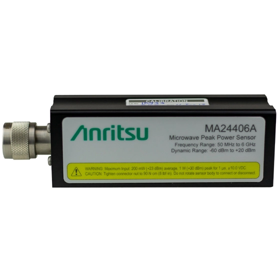
USB peak power sensor covering 50 MHz to 6 GHz with 195 MHz video bandwidth, 3 ns rise time and –60 dBm to +20 dBm average dynamic range.
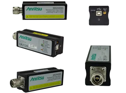
USB peak power sensor covering 50 MHz to 8 GHz with up to 165 MHz video bandwidth and 4 ns rise time.
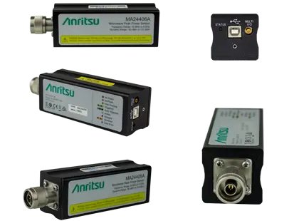
USB peak power sensor covering 50 MHz to 18 GHz with 70 MHz video bandwidth and 5 ns rise time for pulse and modulated signals.
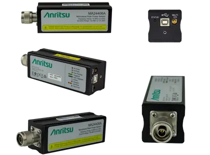
USB microwave peak power sensor covering 50 MHz to 40 GHz with 70 MHz video bandwidth, 5 ns rise time and a K(m) connector.
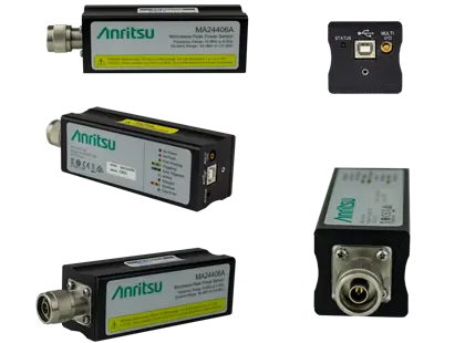
USB peak power sensor covering 50 MHz to 40 GHz with -50 dBm to +20 dBm average dynamic range and a K(m) connector.
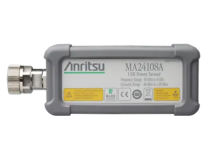
True-RMS USB power sensor measuring average power from 10 MHz to 8 GHz over 60 dB of dynamic range, with internal and external triggering.
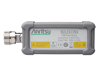
True-RMS USB power sensor measuring average power from 10 MHz to 18 GHz over a 60 dB dynamic range.
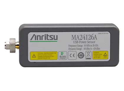
True-RMS USB power sensor measuring average power from 10 MHz to 26 GHz over a 60 dB dynamic range.
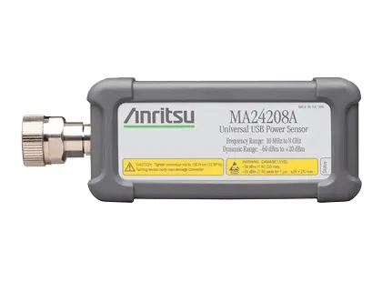
True-RMS USB power sensor measuring average power from 10 MHz to 8 GHz over an 80 dB dynamic range with no benchtop meter required.
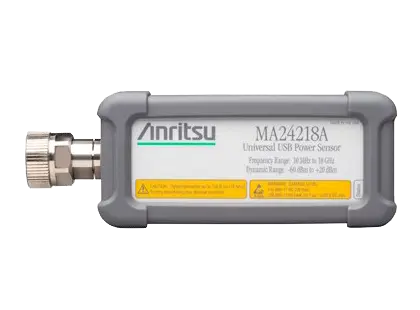
True-RMS USB power sensor measuring average power from 10 MHz to 18 GHz over an 80 dB dynamic range (−60 dBm to +20 dBm).
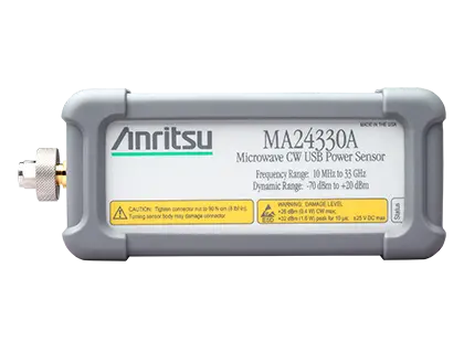
Microwave CW USB power sensor measuring average power from 10 MHz to 33 GHz over a 90 dB dynamic range.
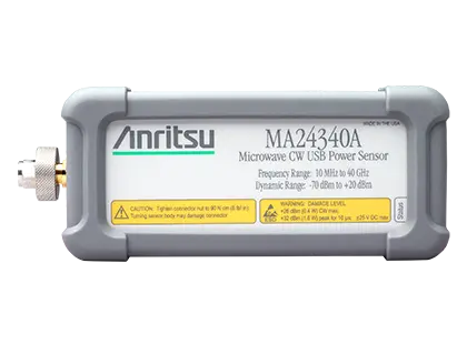
Microwave CW USB power sensor measuring average power from 10 MHz to 40 GHz over a 90 dB dynamic range with a K(m) connector.
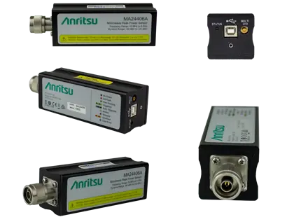
USB peak power sensor covering 50 MHz to 18 GHz with -50 dBm to +20 dBm average dynamic range and 6 MHz video bandwidth.
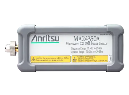
USB power sensor for CW average power measurements from 10 MHz to 50 GHz over a 90 dB dynamic range, with no zeroing required for most signals.