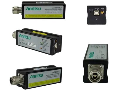
Anritsu MA24418A Microwave Peak USB Power Sensor, 50 MHz to 18 GHz
USB peak power sensor covering 50 MHz to 18 GHz with 70 MHz video bandwidth and 5 ns rise time for pulse and modulated signals.
- Frequency Range
- 50 MHz to 18 GHz
- Dynamic Range (Average)
- -34 dBm to +20 dBm
- Dynamic Range (Pulse)
- -24 dBm to +20 dBm
- Input Damage Level
- +23 dBm, ±10.0 VDC (+30 dBm peak for 1 µs), minimum
Overview
The Anritsu MA24418A is a microwave peak power sensor in the MA24400A USB Peak Power Sensor series. It covers 50 MHz to 18 GHz and connects to a PC over USB, which removes the need for a separate power meter. In fast mode it has a video bandwidth of 70 MHz and a rise time of 5 ns, so it can measure the peak power of wideband modulated signals and narrow pulses.
The sensors process measurements in parallel instead of one step after another. Power readings are processed in real time, which reduces re-arm gaps and missed data during capture. The sensor samples continuously at 100 MSa/s and reaches an effective sampling rate of 10 GSa/s, giving 100 ps time resolution for rising- and falling-edge measurements.
Software
The supplied PC software, Microwave Peak Power Analyzer, is used to configure the sensor and display results. It offers peak and average power readouts, a trace view for pulse power analysis, CCDF graphs, and crest factor and other statistical measurements. Measurements can be synchronized across several sensors.
Key Features
- 50 MHz to 18 GHz frequency range
- 70 MHz video bandwidth with 5 ns rise time (fast mode)
- 100,000 measurements per second
- Real-time processing of power readings
- 100 MSa/s continuous and 10 GSa/s effective sample rates
- 100 ps time resolution for rising/falling edge measurements
- Full pulse profiling
- Crest factor, CCDF and statistical measurements
- Synchronized multi-channel measurements
- Microwave Peak Power Analyzer measurement and analysis software
- USB 2.0 high speed interface to host PC
Specifications
| Frequency Range | 50 MHz to 18 GHz |
|---|---|
| Dynamic Range (Average) | -34 dBm to +20 dBm |
| Dynamic Range (Pulse) | -24 dBm to +20 dBm |
| Input Damage Level | +23 dBm, ±10.0 VDC (+30 dBm peak for 1 µs), minimum |
| Maximum Input |
200 mW (+23 dBm) average, 1 W (+30 dBm) peak for 1 μs, ±10.0 VDC
Warning label
|
| VSWR, 50 MHz to 2 GHz | 1.15:1 |
|---|---|
| VSWR, >2.0 GHz to 16 GHz | 1.28:1 |
| VSWR, >16 GHz to 18 GHz | 1.34:1 |
| Sampling Rate |
100 MSa/s
characteristic
|
|---|---|
| Effective Sampling Rate |
10 GSa/s
characteristic
|
| Single Channel Rise Time (Fast) | 5 ns |
| Single Channel Rise Time (Standard) | <10 µs |
| Video Bandwidth (Fast) | 70 MHz |
| Video Bandwidth (Standard) | 350 kHz |
| Single Shot Bandwidth | 35 MHz |
| Minimum Pulse Width, Dynamic Range | -10 dBm to +20 dBm |
| Minimum Pulse Width (Fast) | 10 ns |
| Minimum Pulse Width (Standard) | 3 µs |
| Source | Continuous, Internal, External TTL, Crossover (from another sensor) |
|---|---|
| Arm Type | Continuous, Single, Trigger Holdoff, Frame (gap) Holdoff |
| Slope | Positive or Negative |
| Trigger Hold Off | 100 ns to 1 s with 10 ns resolution |
| External Trigger Input | SMB (female) |
|---|---|
| Impedance | 10 kΩ |
| Type | TTL |
| High Level Input Voltage | 2.4 V min, 5.5 V max |
| Low Level Input Voltage | -0.1 V min, 0.7 V max |
| Latency |
< 10 ns
Time delay between the defined edge of the applied trigger and the sensor switching into the triggered state
|
| Trigger Pulse Width | 10 ns min |
| Trigger Repetition Period | 20 ns min |
| Processor | 1.3 GHz or higher recommended |
|---|---|
| RAM | 512 MB (1 GB or more recommended) |
| Operating System | Microsoft® Windows® 7 to 10 (32-bit and 64-bit) |
| Hard-Disk Free Space | Min 1.0 GB free space to install and run |
| Display Resolution | 800 x 600 (1280 x 1024 or higher recommended) |
| Interface | USB 2.0 high speed |
| Interface to Host | USB 2.0 high speed |
|---|---|
| RF Connector |
N male to 20 GHz
Listed as N(m) on the product page
|
| Size | 145 mm x 43 mm x 43 mm, excluding N connector |
| Weight | 363 g (0.80 lb) |
| Connector Torque |
90 N·cm (8 lbf·in)
Do not rotate sensor body to connect or disconnect
|
| Warm-Up Time | 60 minutes |
| Calibration Cycle | Anritsu recommended calibration interval is 12 months. |
| Warranty | 1 year from the date of shipment |
| Test Standard | Tests were performed per MIL-28800F (Class3). |
|---|---|
| Operating Temperature Range | 0 ºC to 55 ºC |
| Storage Temperature Range | -40 ºC to +70 ºC |
| Relative Humidity (non-condensing) | 45 % at 50 ºC; 75 % at 40 ºC; 95 % at 30 ºC |
| Altitude | 3048 m operational max |
| Shock | 30 g half-sine, 11 ms duration |
| Vibration | Sinusoidal: 5 Hz to 55 Hz, 3 g max; Random: 10 Hz to 500 Hz, 2.34 g rms; Power Spectral Density: 0.01 g²/Hz |
| EMC Directive |
2014/30/EU, EN 61326:2013
European Union
|
|---|---|
| Emissions | CISPR 11/EN 55011:2019+A1:2010 Class A Equipment |
| Immunity | IEC/EN 61000-4-2/3/4/6 |
| Low Voltage Directive | 2014/35/EU, EN 61010-1:2001 |
| RoHS Directive | 2015/863/EU |
Specifications are taken from the manufacturer's documentation. See the datasheet for complete and current values.
Applications
- Radar systems
- Pulsed communication
- Aerospace and defense
- Electronic warfare system testing
- Component testing
- High-power microwave (HPM) applications
- Wideband modulated signal measurement
Included
- 11410-00976 Information Card
- 806-391-R 1.8 m USB A (m) to USB B (m) cable
Options & Accessories
| Option | Description |
|---|---|
| MA24418A-097 | Accredited Calibration to ISO/IEC 17025 and ANSI/NCSL Z540-1 or ANSI/NCSL Z540.3 — Includes test report, uncertainty data, and accreditation symbol |
| 3-1010-122 | Attenuator, 20 dB, 5 W, DC to 12.4 GHz, N(m) to N(f) |
| 42N50-20 | Attenuator, 20 dB, 5 W, DC to 18 GHz, N(m) to N(f) |
| 3-1010-123 | Attenuator, 30 dB, 50 W, DC to 8.5 GHz, N(m) to N(f) |
| 42N50A-30 | Attenuator, 30 dB, 50 W, DC to 18 GHz, N(m) to N(f) |
| 3-1010-124 | Attenuator, 40 dB, 100 W, DC-8.5 GHz, N(f) input to N(m) output, Unidirectional |
| 34NFK50 | Precision Adapter, DC to 18 GHz, N(f) to K(m), 50Ω |
| 34NK50 | Precision Adapter, DC to 18 GHz, N(m) to K(m), 50Ω |
| 34NKF50 | Precision Adapter, DC to 18 GHz, N(m) to K(f), 50Ω |
| 33NFNF50B | Calibration Grade Adapter, DC to 18 GHz, N(f) to N(f), 50Ω |
| 33NNF50B | Calibration Grade Adapter, DC to 18 GHz, N(m) to N(f), 50Ω |
| 34NN50A | Calibration Grade Adapter, DC to 18 GHz, N(m) to N(m), 50Ω |
| 1091-26-R | Adapter, SMA(m) to N(m), DC to 18 GHz, 50Ω |
| 1091-27-R | Adapter, SMA(f) to N(m), DC to 18 GHz, 50Ω |
| 1091-80-R | Adapter, SMA(m) to N(f), DC to 18 GHz, 50Ω |
| 1091-81-R | Adapter, SMA(f) to N(f), DC to 18 GHz, 50Ω |
| 510-90-R | Adapter, 7/16 DIN(f) to N(m), DC to 7.5 GHz, 50Ω |
| 510-91-R | Adapter, 7/16 DIN(f) to N(f), DC to 7.5 GHz, 50Ω |
| 510-92-R | Adapter, 7/16 DIN(m) to N(m), DC to 7.5 GHz, 50Ω |
| 510-93-R | Adapter, 7/16 DIN(m) to N(f), DC to 7.5 GHz, 50Ω |