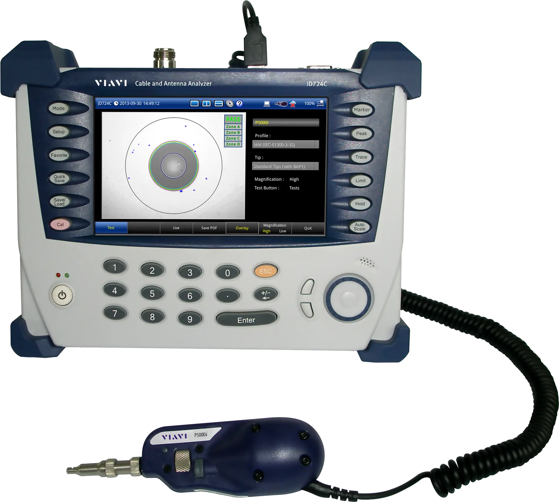
CellAdvisor JD725C Cable and Antenna Analyzer, 5 MHz to 4 GHz with 2-Port Transmission
Handheld cable and antenna analyzer covering 5 MHz to 4 GHz with 1-port and 2-port RF tests, RF/optical power measurement and fiber inspection.
- Frequency range
- 5 MHz – 4 GHz
- Resolution
- 10 kHz
- Accuracy
- ±5 ppm at 25°C
- Aging per year
- ± 1.5 ppm
Overview
The VIAVI CellAdvisor JD725C is a handheld cable and antenna analyzer in the JD720C series, covering 5 MHz to 4 GHz. It combines line sweep measurement, RF and optical power measurement, and fiber inspection in one instrument intended for cell site installation and maintenance.
The JD725C performs the 1-port measurements used to characterize cell-site cable and antenna systems, including VSWR or return loss reflection, distance to fault (DTF), cable loss, 1-port phase and Smith chart. On the JD725C, 2-port transmission is standard, adding insertion gain/loss and 2-port phase measurements for RF components such as filters, jumpers, splitters, amplifiers, duplexers and combiners, as well as antenna and sector-to-sector isolation and TMA verification.
For fiber-fed sites, the analyzer interfaces with the VIAVI P5000i fiber microscope for connector inspection with pass/fail indication and with VIAVI MP-60/MP-80 USB optical power meters. RF power is measured with external JD730 series USB power sensors or serial-connected RF power sensors.
The instrument uses a 7-inch color touch-screen display with an outdoor mode for direct sunlight and a night-display mode, and is built to MIL-PRF-28800F Class 2 for shock and vibration. Optional features include a built-in bias tee, a high-power CW signal generator, Bluetooth, WiFi and USB GPS connectivity, and TestWizard for self-guided test procedures. JDViewer and JDRemote PC software support post-analysis, reporting and remote control.
Key Features
- RF and fiber testing in a single solution
- 2-port transmission and 2-port phase measurements standard on JD725C
- Detect signal degradation over time with Trace Overlay of up to four traces
- Reduce test time by making two measurements simultaneously on one display
- Instant problem notification with simple PASS/FAIL indications
- Faster and easier calibration with EZ-Cal
- Inspect fiber with PASS/FAIL indications using P5000i fiber microscope
- Measure RF and optical power using power sensors
- Three zoom zones for detailed analysis on multi-frequency bands
- Up to 40 dBm (10 W) RF port protection
- Generate PDF/HTML reports
- Automatically saves events that exceed pre-defined limits
- Application software for post-analysis (JDViewer) and remote control (JDRemote)
- Web-based remote control via Bluetooth and Wi-Fi
- Self-guided systematic test procedures with TestWizard
- Database of over 80 wireless frequency bands and over 95 cable types
- Standard, multi-segment and window limit lines with pass/fail indication
- Up to six markers for trace analysis
- Multilanguage user interface
Specifications
| Frequency range | 5 MHz – 4 GHz |
|---|---|
| Resolution | 10 kHz |
| Accuracy | ±5 ppm at 25°C |
| Aging per year | ± 1.5 ppm |
| Data points | 126, 251, 501, 1001, 2001 |
|---|---|
| Measurement speed, reflection | < 0.7 ms/point |
| Measurement speed, DTF | < 0.8 ms/point |
| Corrected directivity (OSL calibration) |
>42 dB (typical)
After OSL calibration, using recommended calibration kits; available only for serial number KR31659001 and later
|
|---|---|
| Corrected directivity (EZ-Cal calibration) |
≤ 4 GHz: >38 dB (typical)
After EZ-Cal calibration
|
| Reflection uncertainty |
±(0.3 + |20log (1 + 10^(-EP/20))|) (typical)
EP = directivity – measured return loss
|
| Output power, high | 0 dBm (nominal) |
|---|---|
| Output power, low | –30 dBm (nominal) |
| Maximum input level, average continuous power | +25 dBm (nominal) |
| Maximum input level, DC voltage | ±50 V DC |
| VSWR range | 1 to 65 |
|---|---|
| VSWR resolution | 0.01 |
| Return loss range | 0 to 60 dB |
| Return loss resolution | 0.01 dB |
| Vertical VSWR range | 1 to 65 |
|---|---|
| Vertical VSWR resolution | 0.01 |
| Vertical return loss range | 0 to 60 dB |
| Vertical return loss resolution | 0.01 dB |
| Horizontal range | 0 to (# of data points – 1) x horizontal resolution; Maximum = 1500 m (4921 ft) |
| Horizontal resolution |
(1.5 x 10^8) x (VP)/delta
VP = propagation velocity; delta = stop frequency – start frequency (Hz)
|
| 1-port cable loss range | 0 to –30 dB |
|---|---|
| 1-port cable loss resolution | 0.01 dB |
| 1-port phase |
–180 to +180°
Listed as 'Resolution' in the datasheet
|
| Smith chart resolution | 0.01° |
| Output power, high | 0 dBm (typical) |
|---|---|
| Output power, low | –30 dBm (typical) |
| Measurement speed, vector | < 1.3 ms/point |
| Dynamic range, vector |
5 MHz to 3 GHz: 80 dB at average 5; 3 GHz to 6 GHz: 75 dB at average 5
Shared JD725C/JD726C specification; JD725C frequency range ends at 4 GHz
|
| Insertion loss/gain range | –120 to +100 dB |
| Insertion loss/gain resolution | 0.01 dB |
| 2-port phase range | –180° to +180° |
| 2-port phase resolution | 0.01° |
|
Voltage range
JD720C001
|
+12 to +32 V
Supplied on the RF-In port
|
|---|---|
|
Voltage resolution
JD720C001
|
1 V |
|
Current
JD720C001
|
250 mA at +32 V, 500 mA at +12 V |
|
Output power range
JD720C005
|
5 MHz to 4 GHz, –30 to +10 dBm |
|---|---|
|
Step
JD720C005
|
1 dB |
|
Accuracy
JD720C005
|
±1.5 dB
20 to 30°C
|
| RF power meter display range |
–80 to +120 dBm
Standard; requires external RF power sensor
|
|---|---|
| RF power meter offset range | 0 to 60 dB |
| RF power meter resolution | 0.01 dB or 0.1 x W (x = m, u, p) |
| Optical power meter display range |
–100 to +100 dBm
Standard; requires external optical power meter
|
| Optical power meter offset range | 0 to 60 dB |
| Optical power meter resolution | 0.01 dB or 0.1 mW |
|
Bluetooth connectivity
JD720C003
|
Personal area network (PAN); File transfer profile (FTP) interface |
|---|---|
|
WiFi interface type
JD720C006
|
USB LAN Card |
|
WiFi interface standard
JD720C006
|
IEEE 802.11 b/g/n |
|
Web-based remote control
JD720C003, JD720C006
|
Internet Explorer, Chrome, Safari |
|
USB GPS location
JD720C004
|
Latitude and longitude on display |
|
USB GPS interface
JD720C004
|
USB 2.0 |
| RF In connector | Type-N, female |
|---|---|
| RF In impedance | 50 Ω (nominal) |
| RF In damage level | > +25 dBm, > ±50 V DC |
| Reflection/RF Out connector | Type-N, female |
| Reflection/RF Out impedance | 50 Ω (nominal) |
| Reflection/RF Out damage level | > +40 dBm, > ±50 V DC (nominal) |
| USB host |
Type A, 2 ports
Connects flash drive, power sensor, P5000i, Bluetooth adapter, WiFi LAN card, or GPS receiver
|
| USB client |
Mini B, 1 port
Connects to PC/laptop for data transfer
|
| LAN | RJ45, 10/100Base-T |
| Serial |
9-pin D-SUB male
For JD72450551/JD72450552
|
| Type | Resistive touch screen |
|---|---|
| Size | 7-inch, LED backlight, transflective LCD |
| Resolution | 800 x 480 |
| Speaker | Built-in speaker |
| External DC input | 12 to 15 VDC |
|---|---|
| Power consumption | 15 W; 37.5 W maximum (when charging battery) |
| AC power adapter input | 100 to 250 V (50 to 60 Hz, 1.2 A) |
| AC power adapter output | 15 V DC, 4 A |
| Battery type | 10.8 V, 7800 mA/hr (LiON) |
| Battery operation time | >5.5 hr (typical) Bias-T off, > 3 hr Bias-T on (Max) |
| Battery charge time | 3 hr (80%), 5 hr (100%) |
| Battery charging temperature | 0 to 45°C (32 to 104°F) ≤85% RH |
| Battery discharging temperature | –20 to 55°C (4 to 131°F) ≤85% RH |
| Battery storage temperature |
0 to 25°C (32 to 77°F) ≤95% RH (noncondensing)
20 to 85% RH, store battery pack in low-humidity environment; extended exposure above 45°C could significantly degrade battery performance and life
|
| Internal |
Maximum 500 MB
Up to 21,000 traces (JD725C/JD726C)
|
|---|---|
| External |
Limited by size of USB flash drive
Supports USB 2.0-compatible memory devices
|
| Operating temperature, AC power | 0 to 40°C (32 to 104°F) with no derating |
|---|---|
| Operating temperature, battery | 0 to 40°C (32 to 104°F) at charging; –10 to 55°C (14 to 131°F) at discharging |
| Maximum humidity | 95% RH (noncondensing) |
| Storage temperature |
–40 to 70°C (–40 to +158°F)
With the battery pack removed
|
| Shock and vibration | MIL-PRF-28800F Class 2 |
| Size (W x H x D) |
260 x 190 x 60 mm (10.2 x 7.5 x 2.4 in)
With battery
|
|---|---|
| Weight |
2.50 kg (5.51 lb)
With battery
|
| Calibration cycle | 2 years |
Specifications are taken from the manufacturer's documentation. See the datasheet for complete and current values.
Applications
- Verification of cell-site cable and antenna systems
- Testing distributed radios with RF and fiber feed-lines
- DAS deployment validation
- NFC antenna testing (RFID and security equipment)
- Antenna and sector-to-sector isolation testing
- TMA, duplexer and combiner verification
Included
- AC/DC power adapter
- Cross LAN cable
- USB A to Mini B cable
- USB memory
- Automotive cigarette lighter/12 V DC adapter
- Rechargeable LiON battery
- Stylus pen
- Soft carrying case
- JD720C series user's manual and application software
Options & Accessories
| Option | Description |
|---|---|
| JD720C001 | Bias tee — Built-in bias tee supplying 12 to 32 V in 1 V steps on the RF-In port |
| JD720C002 | 2-port transmission — Standard for JD725C; requires 2-port calibration kit |
| JD720C003 | Bluetooth connectivity — Includes a USB Bluetooth dongle and dipole antenna (JD70050006) |
| JD720C004 | USB GPS connectivity — Includes a USB GPS receiver |
| JD720C005 | High-power CW signal generator — CW source for small cell coverage or DAS path loss testing |
| JD720C006 | WiFi connectivity — Includes a WiFi dongle (JD70050008) |
| JD720C007 | TestWizard — Self-guided test procedures created in Test Wizard Creator |
| JD78050509 | Y-calibration kit Type-N(m), DC to 6 GHz, 50 Ω |
| JD78050510 | Y-calibration kit DIN(m), DC to 6 GHz, 50 Ω |
| JD78050507 | Dual-port Type-N(m) 6 GHz calibration kit — Includes 1x JD78050509 Y-calibration kit, 2x G700050530 RF Cable, and 2x G700050575 RF Adapter Type-N(f) to Type-N(f) |
| JD78050508 | Dual-port DIN(m) 6 GHz calibration kit — Includes 1x JD78050510 DIN Y-calibration kit, 2x G710050536 RF Cable, and 2x G700050572 RF Adapter DIN(m) to DIN(m) |
| JD70050509 | Electronic calibration kit (EZ-Cal) |
| JD731B | Directional power sensor (peak and average), 300 MHz to 3.8 GHz, average 0.15 to 150 W, peak 4 to 400 W |
| JD733A | Directional power sensor (peak and average), 150 MHz to 3.5 GHz, average/peak 0.1 to 50 W |
| JD732B | Terminating power sensor (average), 20 MHz to 3.8 GHz, –30 to +20 dBm |
| JD734B | Terminating power sensor (peak), 20 MHz to 3.8 GHz, –30 to +20 dBm |
| JD736B | Terminating power sensor (peak and average), 20 MHz to 3.8 GHz, –30 to +20 dBm |
| MP-60A | USB optical power meter with software, 2.5 and 1.25 mm interfaces, 30-inch USB extender, and carrying pouch |
| MP-80A | USB optical power meter — high power, with software, 2.5 and 1.25 mm interfaces, 30-inch USB extender, and carrying pouch |
| FBP-SD101 | KIT: FBP-P5000i digital probe, FiberChekPRO software, case, and four tips |
| FIT-SD103 | KIT: FBP-P5000i digital probe, MP-60A USB power meter, FiberChekPRO software, case, tips, and adapters |
| JD72050522 | JD720C AC/DC adapter for JD725C and JD726C |
| JD70050542 | JD720 hard carrying case with wheels |
| G710550324 | External battery charger |
| JD725/6-EW | JD725C/726C warranty extension |
| JD725-CP | 1 Calibration over 1 year period for JD725 |
| JD725/726-CAL | Certified calibration for JD725/726 |
| JD720C100 | Certificate of calibration with test data for new instrument |
Documents & Resources
Related Products
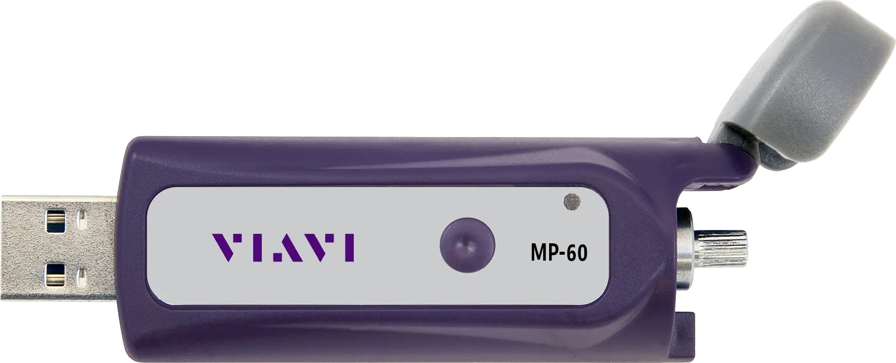
Miniature optical power meter that measures optical power over a USB 2.0 connection to a PC, laptop or smart device.
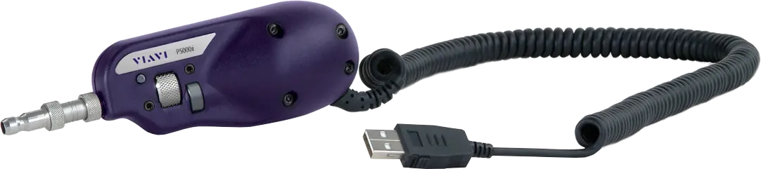
Handheld digital fiber microscope that automatically inspects and certifies fiber connector end faces with pass/fail analysis to industry standards.