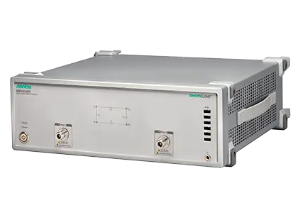
ShockLine MS46522B 2-Port Performance Vector Network Analyzer
2-port ShockLine performance VNA for S-parameter and time domain measurements of passive devices from 50 kHz to 43.5 GHz and in E-band to 92 GHz.
- Operating frequency
- 50 kHz to 8.5 GHz
- Operating frequency
- 50 kHz to 20 GHz
- Operating frequency
- 50 kHz to 43.5 GHz
- Operating frequency
- 55 GHz to 92 GHz, one meter tethers
Overview
The Anritsu ShockLine MS46522B is a 2-port performance vector network analyzer in a 3U high chassis. It measures S-parameters and time domain characteristics of passive RF and microwave devices. Typical uses include manufacturing and verification of 5G mmWave network equipment and devices, automotive cables, high-speed data interconnects and system integration components.
The base model requires one frequency option. Options 10, 20 and 43 cover 50 kHz to 8.5 GHz, 20 GHz and 43.5 GHz respectively. Options 82 and 83 cover the extended E-band from 55 GHz to 92 GHz using tethered source/receiver modules that connect directly to the device under test: Option 82 uses 1 meter tethers for bench-top use, and Option 83 uses 5 meter tethers for over-the-air (OTA) chamber installations. The E-band options must be ordered and factory-installed on new units.
Option 2 adds real-time bandpass and lowpass time domain analysis with time gating. Lowpass mode gives a TDR-like display of impedance over distance or time. Option 24, Universal Fixture Extraction, adds de-embedding tools for test fixture extraction. On the 8.5 GHz model, Option 61 adds bias tees on ports 1 and 2 to supply DC bias to the device during test.
The instrument has an embedded computer and power supply. It is controlled remotely over LAN using SCPI commands, and a full graphical user interface is available when a user-supplied touchscreen monitor, keyboard and mouse are attached. The GUI, command syntax, drivers and programming environments are shared with the rest of the ShockLine family.
Key Features
- Guaranteed performance to 43.5 GHz with Extended K ports
- High output power for measuring high attenuation devices
- Wide dynamic range for measuring very low reflection artifacts
- Corrected directivity that minimizes measurement uncertainty
- SmartCal auto calibration unit support to reduce calibration and setup time
- Time domain with time gating option for fault identification
- LAN interface for remote control
- Common GUI and SCPI interface across the ShockLine family
- Bias tee option for DUTs that need DC biasing
- Universal Fixture Extraction (UFX) software option for test fixture de-embedding
- E-band coverage from 55 GHz to 92 GHz, covering E-band and major parts of V band
- Fully assembled E-band test system with tethered modules that connect directly to the DUT
Specifications
|
Operating frequency
MS46522B-010
|
50 kHz to 8.5 GHz |
|---|---|
|
Operating frequency
MS46522B-020
|
50 kHz to 20 GHz |
|
Operating frequency
MS46522B-043
|
50 kHz to 43.5 GHz |
|
Operating frequency
MS46522B-082
|
55 GHz to 92 GHz, one meter tethers
No implied or warranted specifications from 55 GHz to 60 GHz and from 90 GHz to 92 GHz
|
|
Operating frequency
MS46522B-083
|
55 GHz to 92 GHz, five meter tethers
No implied or warranted specifications from 55 GHz to 60 GHz and from 90 GHz to 92 GHz
|
|
E-band waveguide flange
MS46522B-082, MS46522B-083
|
WR-12
Extended E-Band, 55 GHz to 92 GHz
|
| Frequency resolution | 1 Hz |
| Frequency accuracy |
± 0.1 ppm
At time of calibration
|
| Frequency stability over temperature |
± 0.1 ppm/10 °C to 50 °C
Typical
|
| Frequency stability (aging) |
± 0.02 ppm/24 hours; ± 0.2 ppm/1 month; ± 1.0 ppm/1 year; ±2.0 ppm/3 years
Typical
|
| Dynamic range | 140 dB maximum |
|---|---|
| Sweep speed | 30 μsec/point |
| Directivity | 50 dB maximum |
|
50 kHz to 1 MHz
MS46522B-010
|
90 dB
Typical 101 dB; 10 Hz IF bandwidth
|
|---|---|
|
> 1 MHz to 50 MHz
MS46522B-010
|
100 dB
Typical 108 dB
|
|
> 50 MHz to 1.8 GHz
MS46522B-010
|
140 dB
Typical 144 dB
|
|
> 1.8 GHz to 4 GHz
MS46522B-010
|
137 dB
Typical 142 dB
|
|
> 4 GHz to 6 GHz
MS46522B-010
|
130 dB
Typical 137 dB
|
|
> 6 GHz to 8 GHz
MS46522B-010
|
128 dB
Typical 130 dB
|
|
> 8 GHz to 8.5 GHz
MS46522B-010
|
120 dB
Typical 127 dB
|
|
50 kHz to 1 MHz
MS46522B-020, MS46522B-043
|
90 dB
Typical 101 dB; 10 Hz IF bandwidth
|
|---|---|
|
> 1 MHz to 50 MHz
MS46522B-020, MS46522B-043
|
100 dB
Typical 108 dB
|
|
> 50 MHz to 1.8 GHz
MS46522B-020, MS46522B-043
|
140 dB
Typical 144 dB
|
|
> 1.8 GHz to 4 GHz
MS46522B-020, MS46522B-043
|
137 dB
Typical 142 dB
|
|
> 4 GHz to 6 GHz
MS46522B-020, MS46522B-043
|
130 dB
Typical 137 dB
|
|
> 6 GHz to 8 GHz
MS46522B-020, MS46522B-043
|
122 dB
Typical 124 dB
|
|
> 8 GHz to 8.5 GHz
MS46522B-020, MS46522B-043
|
118 dB
Typical 122 dB
|
|
> 8.5 GHz to 12 GHz
MS46522B-020, MS46522B-043
|
114 dB
Typical 120 dB
|
|
> 12 GHz to 25 GHz
MS46522B-020, MS46522B-043
|
117 dB
Typical 122 dB
|
|
> 25 GHz to 40 GHz
MS46522B-043
|
119 dB
Typical 126 dB
|
|
> 40 GHz to 43.5 GHz
MS46522B-043
|
110 dB
Typical 120 dB
|
| 50 kHz to 300 kHz |
+10 dBm
0.2 dB compression, 300 Hz IF bandwidth; characteristic performance
|
|---|---|
| > 300 kHz to 8 GHz |
+15 dBm
8.5 GHz for Option 10; characteristic performance
|
| > 8 GHz to 43.5 GHz |
+10 dBm
Characteristic performance
|
| 50 kHz to 300 kHz |
0.034 dB, 0.15 deg
Typical 0.01 dB, 0.08 deg; 100 Hz IF bandwidth, default power, RMS
|
|---|---|
| > 300 kHz to 1 GHz |
0.0055 dB, 0.04 deg
Typical 0.003 dB, 0.02 deg; may be degraded in a 100 MHz window about 1 GHz by up to 0.003 dB rms
|
| > 1 GHz to 25 GHz |
0.0055 dB, 0.05 deg
Typical 0.002 dB, 0.02 deg
|
| > 25 GHz to 43.5 GHz |
0.004 dB, 0.05 deg
Typical 0.002 dB, 0.04 deg
|
| Output power range, 50 kHz to 300 kHz |
-30 to +5 dBm
Typical -30 to +10 dBm
|
|---|---|
| Output power range, > 300 kHz to 6 GHz |
-30 to +15 dBm
Typical -30 to +17 dBm
|
| Output power range, > 6 GHz to 8 GHz |
-30 to +12 dBm
Typical -30 to +13 dBm; maximum power degrades by 2 dB for Options 20 and 43
|
| Output power range, > 8 GHz to 8.5 GHz |
-30 to +10 dBm
Typical -30 to +11 dBm
|
|
Output power range, > 8.5 GHz to 40 GHz
MS46522B-020, MS46522B-043
|
-30 to +6 dBm
Typical -30 to +9 dBm
|
|
Output power range, > 40 GHz to 43.5 GHz
MS46522B-043
|
-30 to +2 dBm
Typical -30 to +4 dBm
|
| Default output power |
0 dBm
Not applicable to MS46522B-08x
|
| Power accuracy at 0 dBm, 50 kHz to 8.5 GHz |
± 1.5 dB
Typical ± 0.5 dB; source is open loop below 300 kHz, ± 2 dB typical
|
| Power accuracy at 0 dBm, > 8.5 GHz to 25 GHz |
± 2.0 dB
Typical ± 0.5 dB
|
| Power accuracy at 0 dBm, > 25 GHz to 40 GHz |
± 2.5 dB
Typical ± 0.5 dB
|
| Power accuracy at 0 dBm, > 40 GHz to 43.5 GHz |
± 3.0 dB
Typical ± 1.0 dB
|
| Power accuracy at -30 dBm |
±3.0 dB
Typical, all frequency bands
|
| Output power setting resolution |
0.01 dB
50 kHz to 43.5 GHz
|
| 50 kHz to 8.5 GHz |
0.02 dB/°C, 0.5 deg/°C
Ratioed measurement, ports shorted; typical
|
|---|---|
| > 8.5 GHz to 40 GHz |
0.01 dB/°C, 1.0 deg/°C
Typical
|
| > 40 GHz to 43.5 GHz |
0.02 dB/°C, 1.5 deg/°C
Typical
|
|
Harmonics, > 300 kHz to 8 GHz
MS46522B-020, MS46522B-043
|
< -30 dBc
Measured at 0 dBm; typical
|
|---|---|
|
Harmonics, > 20 GHz to 43.5 GHz
MS46522B-020, MS46522B-043
|
< -20 dBc
Typical
|
|
Non-harmonic spurious, > 300 kHz to 43.5 GHz
MS46522B-020, MS46522B-043
|
< -30 dBc
Typical
|
|
Phase noise @ 10 kHz offset, > 20 GHz to 43.5 GHz
MS46522B-020, MS46522B-043
|
< -50 dBc/Hz
Typical
|
| Directivity, 50 kHz to 4 GHz |
> 21 dB
Typical; user correction off, system correction on
|
|---|---|
| Port match, 50 kHz to 4 GHz |
> 17 dB
Typical; worst of source and load match
|
| Directivity, > 4 GHz to 43.5 GHz |
> 15 dB
Typical
|
| Port match, > 4 GHz to 43.5 GHz |
> 15 dB
Typical
|
|
Directivity, > 0.05 GHz to 40 GHz
MS46522B-043
|
≥ 45 dB
12-term SOLT calibration
|
|---|---|
|
Source match, > 30 GHz to 40 GHz
MS46522B-043
|
≥ 42 dB |
|
Directivity, > 40 GHz to 43.5 GHz
MS46522B-043
|
≥ 42 dB |
|
Source match, > 40 GHz to 43.5 GHz
MS46522B-043
|
≥ 41 dB |
|
Load match, > 40 GHz to 43.5 GHz
MS46522B-043
|
≥ 41 dB
Characteristic performance
|
|
Directivity, 50 kHz to 6 GHz
MS46522B-010
|
> 40 dB
12-term SOLT calibration
|
|---|---|
|
Source match, 50 kHz to 8.5 GHz
MS46522B-010
|
> 35 dB |
|
Directivity, > 6 GHz to 8.5 GHz
MS46522B-010
|
> 36 dB |
|
System dynamic range, > 67 GHz to 83 GHz
MS46522B-082, MS46522B-083
|
110 dB
Typical 118 dB
|
|---|---|
|
System dynamic range, > 83 GHz to 87 GHz
MS46522B-082
|
110 dB
Typical 118 dB
|
|
System dynamic range, > 83 GHz to 87 GHz
MS46522B-083
|
98 dB
Typical 104 dB
|
|
High level noise, 60 GHz to 90 GHz
MS46522B-082, MS46522B-083
|
0.004 dB, 0.06 deg
Typical
|
|
Output power range, 60 GHz to 69 GHz
MS46522B-082, MS46522B-083
|
-55 to -5 dBm
Typical
|
|
Output power range, > 69 GHz to 88 GHz
MS46522B-082, MS46522B-083
|
-50 to 0 dBm
Typical
|
|
Output power range, > 88 GHz to 90 GHz
MS46522B-082, MS46522B-083
|
-60 to -10 dBm
Typical
|
|
Power accuracy, 60 GHz to 90 GHz
MS46522B-082, MS46522B-083
|
±2.0 dB
At maximum rated power -5 dB; typical; resolution 0.01 dB
|
|
Mechanical stability, 60 to 90 GHz
MS46522B-082, MS46522B-083
|
±0.1 dB, ±3.0 degrees
Modules moving 100 mm and 15 degrees; typical
|
|
Spur reduction
MS46522B-082, MS46522B-083
|
Option -082 supports turning off the unused test receiver during s-parameter measurements; Option -083 does not |
| 2-port measurements | S11, S21, S22, S12, and any user-defined combination of a1, a2, b1, b2, 1 |
|---|---|
| Domains | Frequency Domain, Time (Distance) Domain (Option 2), Power Domain |
| Frequency sweep types | Linear, Log, CW, or Segmented |
| Maximum data points | 2 to 20,001 points |
| Channels and traces | 16 channels, each with up to 16 traces |
| IF bandwidth | 10, 20, 30, 50, 70, 100, 200, 300, 500, 700 Hz; 1, 2, 3, 5, 7, 10, 20, 30, 70, 100, 200, 300, 500 kHz |
| Averaging | Point-by-point or sweep-by-sweep, maximum number of averages = 4096 |
| Markers | 12 markers + 1 reference marker per trace |
| Calibration methods | SOLT, SOLR, SSLT, SSST, LRL/LRM, TRL/TRM, Source Calibration, Receiver Calibration, SmartCal, AutoCal |
|
Cycle time, 50 kHz to 43.5 GHz, 201 points, 500 kHz IF bandwidth, 2-port cal
MS46522B-043
|
99 ms
Typical; includes retrace time
|
| Chassis |
3U high
Includes computer and power supply
|
|---|---|
| Remote control | SCPI over LAN |
| Recommended calibration cycle | 12 months |
| Warranty | 1 Year |
| EMC Directive | 2014/30/EU |
|---|---|
| Low Voltage Directive | 2014/35/EU |
| RoHS Directive | 2011/65/EU + 2015/863 |
| Emissions | EN 55011:2009 +A1:2010 Group 1 Class A |
| Electrical safety | EN 61010-1:2010 + AMD1:2016 |
Specifications are taken from the manufacturer's documentation. See the datasheet for complete and current values.
Applications
- 5G network components
- UE micro coaxial RF connectors
- UE antennas, switches, diplexers and front end modules
- Automotive RF (FAKRA) connectors
- Driver assistance radar
- Passive device testing
- Connectors and cables
- Switches, attenuators and couplers
- Filters, isolators and circulators
- Phase shifters
- Near-field and far-field antenna measurements
- System calibration and path-loss characterization
- General S-parameter and time domain measurements
- Amplifier characterization
- Wireless power transfer (KQ product, maximum efficiency)
- Photo receiver, laser modulator and optical transceiver measurements
- Material measurements
Options & Accessories
| Option | Description |
|---|---|
| MS46522B-010 | 50 kHz to 8.5 GHz — Frequency option |
| MS46522B-020 | 50 kHz to 20 GHz — Frequency option |
| MS46522B-043 | 50 kHz to 43.5 GHz — Frequency option |
| MS46522B-082 | 55 GHz to 92 GHz, 1 meter tethers — E-band frequency option; factory-installed on new units only |
| MS46522B-083 | 55 GHz to 92 GHz, 5 meter tethers — E-band frequency option for OTA chamber installations; factory-installed on new units only |
| MS46522B-001 | Rack mount — Adds handles and removes feet for shelf-mounting into a 19 in. universal rack |
| MS46522B-002 | Time domain with time gating |
| MS46522B-024 | Universal Fixture Extraction |
| MS46522B-061 | Bias Tees (Port 1 and 2) — For MS46522B units with Option 10 only |
Documents & Resources
Related Products
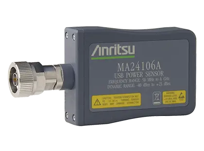
True-RMS USB power sensor that measures average power from 50 MHz to 6 GHz over a 63 dB dynamic range without a separate power meter.
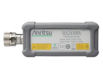
True-RMS USB power sensor measuring average power from 10 MHz to 8 GHz over 60 dB of dynamic range, with internal and external triggering.
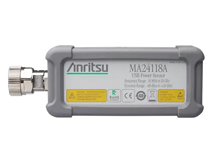
True-RMS USB power sensor measuring average power from 10 MHz to 18 GHz over a 60 dB dynamic range.
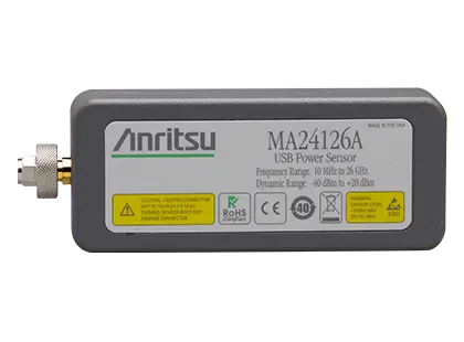
True-RMS USB power sensor measuring average power from 10 MHz to 26 GHz over a 60 dB dynamic range.
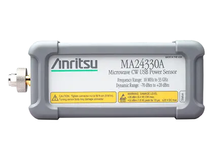
Microwave CW USB power sensor measuring average power from 10 MHz to 33 GHz over a 90 dB dynamic range.
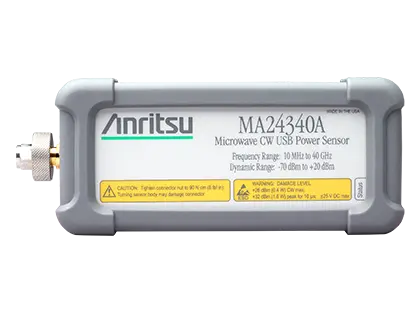
Microwave CW USB power sensor measuring average power from 10 MHz to 40 GHz over a 90 dB dynamic range with a K(m) connector.
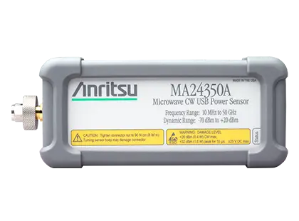
USB power sensor for CW average power measurements from 10 MHz to 50 GHz over a 90 dB dynamic range, with no zeroing required for most signals.