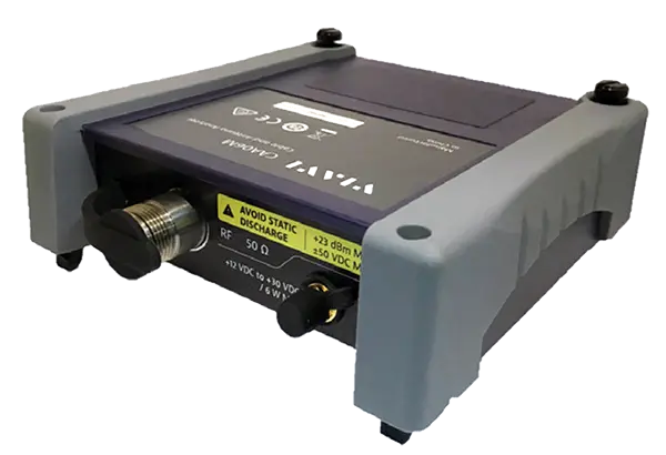
VIAVI CAA06MB 6 GHz Cable and Antenna Analyzer Module with Bias Power and External Bias-Tee
6 GHz cable and antenna analyzer module with bias power and external bias-tee for the VIAVI CellAdvisor 5G and OneAdvisor 800 platforms.
- Frequency range
- 12.5 MHz to 6 GHz
- Frequency resolution
- 1 kHz
- Frequency accuracy
- ±2.5 ppm
- Aging per year
- ±1 ppm
Overview
The VIAVI CAA06MB is a member of the CAA06M family of compact, modular cable and antenna analyzers covering 12.5 MHz to 6 GHz. It is designed to characterize and verify cell-site installations, including feed line systems, and to verify antenna or sector-to-sector isolation.
The CAA06MB version adds bias power and ships with the G700050653 external bias-tee device and cable. Bias voltage from +12 to +30 V DC can be supplied through the module's SMA bias voltage port to an external bias-tee device.
The module works with the CA5000 CellAdvisor 5G and the OneAdvisor 800. CellAdvisor 5G users require the CA5000-DMC dual module carrier, and the module is detected automatically by the main instrument when mounted to the dual module carrier.
Measurements and workflow
Standard modes include reflection (return loss and VSWR), distance to fault, 1-port cable loss, 1-port phase, cable delay, Smith chart and CAA Check. 2-port transmission and an RF CW source are available as software options. Calibration supports standard OSL, EZ-Cal and Quick for 1-port and Thru for 2-port, and results can be reported onboard in PDF, managed through StrataSync, or post-processed with the JDViewer PC application.
Key Features
- Auto file naming that eliminates manual inputs in file name
- Trace overlay that detects signal degradation over time
- Dual display and multiple tabs for fast and efficient measurements
- Intuitive pass/fail analysis that instantly notifies a problem
- Integrated RF CW source
- EZ-Cal™ calibration
- CAA Check, TPA, and Job Manager for test process automation and consolidated reports
- Bias power port with included external bias-tee device and cable
- Auto detectable by main instrument when mounted to dual module carrier
Specifications
| Frequency range | 12.5 MHz to 6 GHz |
|---|---|
| Frequency resolution | 1 kHz |
| Frequency accuracy |
±2.5 ppm
@25°C
|
| Aging per year | ±1 ppm |
| Data points | 126, 251, 501, 1001, 2001 |
| Measurement bandwidth | 10 kHz |
| Corrected directivity (after OSL calibration) | > 42 dB |
|---|---|
| Reflection uncertainty (after OSL calibration) |
±(0.3 + |20log (1 + 10^(-EP/20))|)
typical; EP = directivity – measured return loss
|
| Corrected directivity (after EZ-Cal calibration) | > 38 dB (≤ 4 GHz); > 33 dB (> 4 GHz) |
| Reflection uncertainty (after EZ-Cal calibration) |
±(0.3 + |20log (1 + 10^(-EP/20))|) (≤ 4 GHz); ±(1 + |20log (1 + 10^(-EP/20))|) (> 4 GHz)
typical; EP = directivity – measured return loss
|
| Output power |
0 dBm
nominal
|
|---|---|
| Maximum input level, average continuous power |
23 dBm
nominal
|
| Maximum input level, DC voltage | ±50 V DC |
| Interference immunity, on channel | 15 dBm @ ≥ 1.3 MHz |
| Interference immunity, on frequency | 15 dBm within 100 kHz |
| Measurement speed | 0.5 ms per data point |
|---|---|
| Vertical VSWR range |
1 to 65
Resolution 0.01
|
| Vertical return loss range |
0 to 60 dB
Resolution 0.01 dB
|
| Horizontal range | 0 to (# of data points – 1) x horizontal resolution; Maximum = 1500 m (4921 ft) |
| Horizontal resolution |
(1.5 x 10^8) x (VP)/ΔF
VP = propagation velocity; ΔF = stop frequency – start frequency (Hz)
|
| Measurement speed | 0.5 ms per data point |
|---|---|
| VSWR range |
1 to 65
Resolution 0.01
|
| Return loss range |
0 to 60 dB
Resolution 0.01 dB
|
| 1-port cable loss measurement range |
0 to -30 dB
Resolution 0.01 dB
|
|---|---|
| 1-port phase measurement range |
-180 to +180°
Resolution 0.01°
|
| Smith chart impedance |
50 Ω
Resolution 0.01
|
| Output power range |
-30 to +5 dBm
typical
|
|---|---|
| Output power step | 1 dB |
| Scalar measurement speed |
3.8 ms on CellAdvisor 5G; 6.3 ms on OneAdvisor 800
typical
|
| Dynamic range |
110 dB @average 5 for ≤ 4.5 GHz; 105 dB @average 5 for > 4.5 GHz
typical
|
| Measurement range |
-120 to +100 dB
Resolution 0.01 dB
|
|
Voltage range
CAA06MB
|
+12 to +30 V DC, 6 W max. |
|---|---|
|
Voltage resolution
CAA06MB
|
1 V |
|
Current
CAA06MB
|
500 mA |
| Frequency range | 400 MHz to 6 GHz (tunable down to 13 MHz) |
|---|---|
| Frequency step | 1 MHz |
| Output power range |
-30 to +10 dBm
Output power step 1 dB
|
| Output power accuracy |
±1.5 dB
for 20 to 30°C
|
| Reflection/RF out port connector type |
Type-N, female
Impedance 50 Ω nominal
|
|---|---|
| Reflection/RF out port damage level | 30 dBm max. nominal; ±50 V DC max. nominal |
|
Bias voltage port connector type
CAA06MB
|
SMA, female
For connecting to an external bias-tee device; impedance 50 Ω nominal
|
| Power input | 19 V DC |
|---|---|
| Power consumption |
6.2 W
for CAA06M only, without using external bias-tee
|
| Size (W x H x D) | 130 x 138 x 41 mm (5.12 x 5.43 x 1.65 inch) |
|
Weight
CAA06MB
|
0.45 kg (0.99 lb)
for CAA06M module with bias power port
|
| Operating temperature | -10 to 55°C (14 to 131°F) |
|---|---|
| Storage temperature | -40 to 70°C (-40 to 158°F) |
| Maximum humidity | 95% RH, non-condensing |
| Shock | MIL-PRF-28800F Class 2 |
| Vibration | MIL-PRF-28800F Class 2 |
| Transit drop | MIL-PRF-28800F Class 2 |
| Safety | EN 61010-1:2010, UL 61010-1:2012, CAN/CSA-C22.2 No. 61010-1:2012 |
|---|---|
| EMC | IEC/EN 61326-1:2013, IEC/EN 61326-2-1:2013, CISPR 11:2015 +A1:2016, KN 11, IEC/EN 61000-4-2/3/4/5/6/11, KN 61000-4-2/3/4/5/6/11 |
| RoHS | Compliant |
| Recommended calibration cycle | 2 years |
| Standard modes | Reflection VSWR, Reflection Return Loss, DTF VSWR, DTF Return Loss, 1 Port Cable Loss, 1 Port Phase, Cable Delay, Smith Chart, CAA Check |
|---|---|
| Optional modes | 2 Port Transmission, RF Source |
| Measurement display | Single, dual horizontal, or dual vertical display; Up to 6 independent measurement tabs |
| Trace | Trace overlay, trace math; Trace zoom and up to 4 zoom zones |
| Marker | Up to 6 markers; 3 marker types: normal, delta, and delta pair |
| Limit | Single limit line, multi segment limit line, limit window |
| Calibration type | 1 Port: Standard OSL, EZ-Cal, and Quick; 2 Port: Thru |
| Report generation | Onboard report generation in .pdf |
| Cloud service | StrataSync |
| Post-processing | JDViewer PC application |
Specifications are taken from the manufacturer's documentation. See the datasheet for complete and current values.
Applications
- Cell site installation verification
- Cell site maintenance
- Feed line system characterization
- Antenna isolation verification
- Sector-to-sector isolation verification
Included
- G700050653 external bias-tee device: Bias-Tee, N(m), N(f), BNC(f), 2.5 to 6000 MHz, 1W
- 250 mm BNC(m) to SMA(m) cable for the bias-tee
Options & Accessories
| Option | Description |
|---|---|
| CA5000-DMC | Dual Module Carrier with Dummy Module for CellAdvisor 5G — Includes C10-DMC and C2K-EMPTYMOD; required for CA5000 CellAdvisor 5G users |
| CAA06M-CR | CAA module calibration report |
| CAA06M-CRISO | CAA module calibration report per ISO 17025 |
| CA5000-S005/ONA-CAA-2P | 2 Port transmission measurement — Software option on CellAdvisor 5G/OneAdvisor 800 |
| CA5000-S006/ONA-CAA-RFS | RF CW source — Software option on CellAdvisor 5G/OneAdvisor 800 |
| JD78050507 | Dual port Type-N 6 GHz calibration kit — Includes JD78050509 Y-calibration kit (1), G700050530 RF Cable (2), and G700050575 RF Adapter (2) |
| JD78050508 | Dual port DIN 6 GHz calibration kit — Includes JD78050510 Y-calibration kit (1), G710050536 RF Cable (2), and G700050572 RF Adapter (2) |
| JD78050509 | Y-Calibration kit, Type-N(m), DC to 6 GHz, 50 Ω — Included in JD78050507 |
| JD78050510 | Y-Calibration kit, DIN(m), DC to 6 GHz, 50 Ω — Included in JD78050508 |
| JD70050509 | EZ-Cal kit, Type-N(m), DC to 6 GHz, 50 Ω |
| G700050530 | RF cable DC to 8 GHz Type-N(m) to Type-N(m), 1.0 m — Included in JD78050507 |
| G700050531 | RF cable DC to 8 GHz Type-N(m) to Type-N(f), 1.5 m |
| G700050532 | RF cable DC to 8 GHz Type-N(m) to Type-N(f), 3.0 m |
| G710050536 | RF cable DC to 6 GHz Type-N(m) to DIN(f), 1.5 m — Included in JD78050508 |
| G700050540 | Phase-stable RF cable w grip DC to 6 GHz Type-N(m) to Type-N(f), 1.5 m |
| G700050541 | Phase-stable RF cable w grip DC to 6 GHz Type-N(m) to DIN(f), 1.5 m |
| G700050571 | Adapter Type-N(m) to DIN(f), DC to 7.5 GHz, 50 Ω |
| G700050572 | Adapter DIN(m) to DIN(m), DC to 7.5 GHz, 50 Ω — Included in JD78050508 |
| G700050573 | Adapter Type-N(m) to SMA(f) DC to 18 GHz, 50 Ω |
| G700050574 | Adapter Type-N(m) to BNC(f), DC to 4 GHz, 50 Ω |
| G700050575 | Adapter Type-N(f) to Type-N(f), DC to 18 GHz 50 Ω — Included in JD78050507 |
| G700050576 | Adapter Type-N(m) to DIN(m), DC to 7.5 GHz, 50 Ω |
| G700050577 | Adapter Type-N(f) to DIN(f), DC to 7.5 GHz, 50 Ω |
| G700050578 | Adapter Type-N(f) to DIN(m), DC to 7.5 GHz, 50 Ω |
| G700050579 | Adapter DIN(f) to DIN(f), DC to 7.5 GHz, 50 Ω |
| G700050580 | Adapter Type-N(m) to Type-N(m), DC to 11 GHz 50 Ω |
| G700050581 | Adapter N(m) to QMA(f), DC to 6.0 GHz, 50 Ω |
| G700050582 | Adapter N(m) to QMA(m), DC to 6.0 GHz, 50 Ω |
| G700050583 | Adapter N(m) to 4.1/9.5 MINI DIN(f), DC to 6.0 GHz, 50 Ω |
| G700050584 | Adapter N(m) to 4.1/9.5 MINI DIN(m), DC to 6.0 GHz, 50 Ω |
| G700050585 | Adapter N(m) to 4.3-10(f), DC to 6.0 GHz, 50 Ω |
| G700050586 | Adapter N(m) to 4.3-10(m), DC to 6.0 GHz, 50 Ω |
| G700050587 | Adapter N(f) to SMA(f), DC to 18 GHz, 50 Ω |
| G710050581 | Attenuator 40 dB, 100 W, DC to 4 GHz (unidirectional) |
Documents & Resources
Related Products
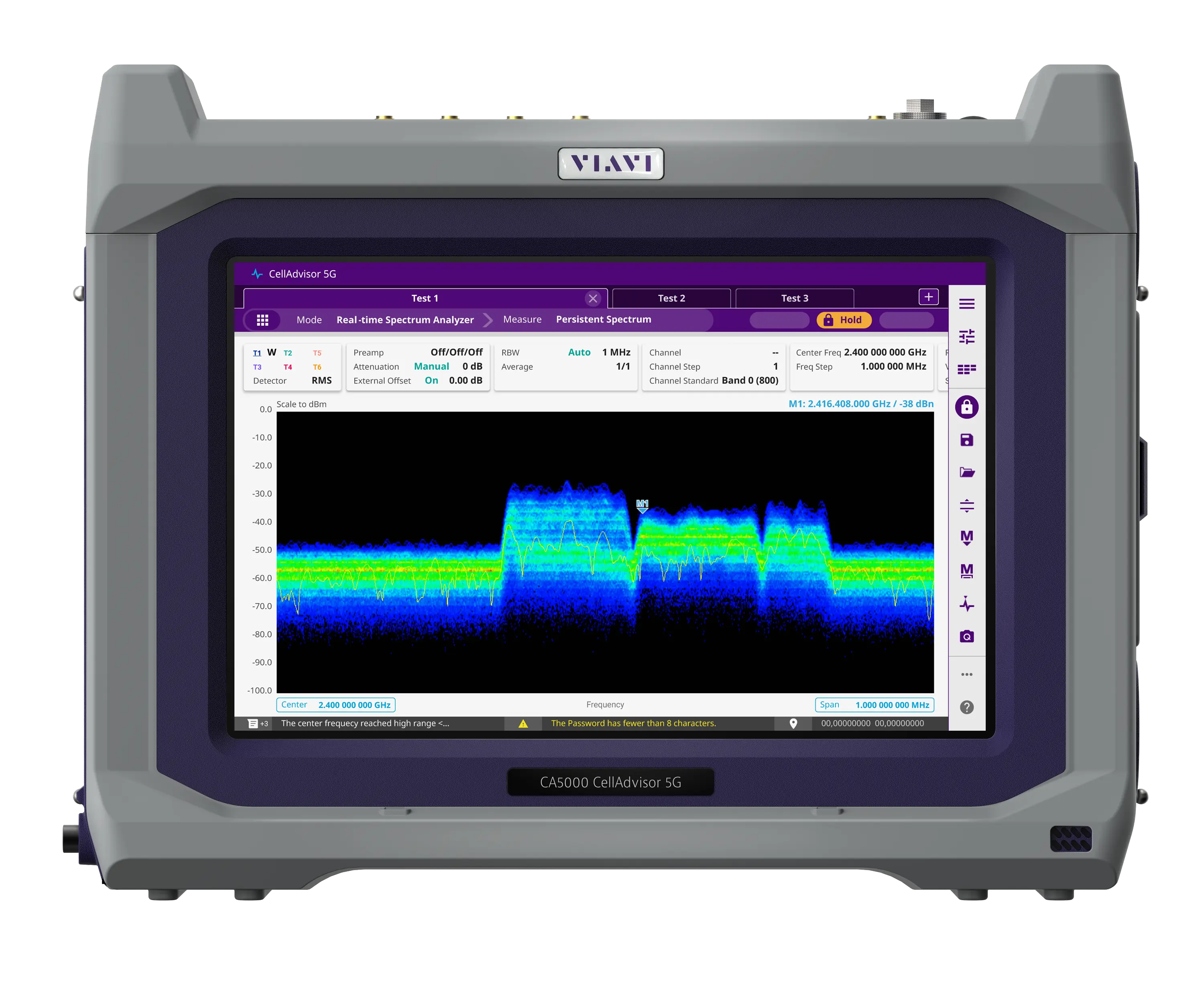
Field-portable base station analyzer with real-time spectrum analysis and 5G NR beam analysis, covering 9 kHz up to 44 GHz depending on frequency option.
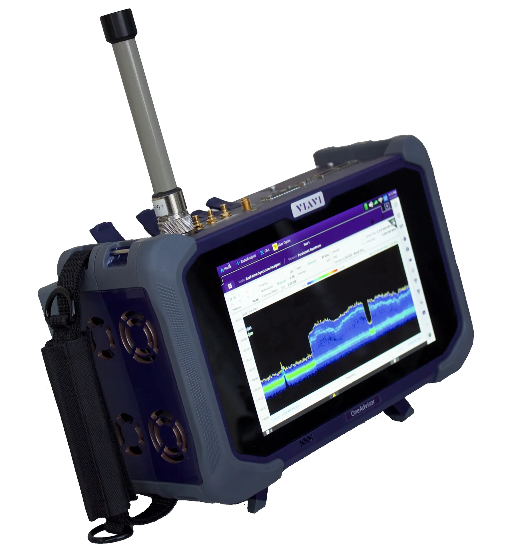
Modular field test platform combining RF spectrum and signal analysis, cable and antenna, fiber and Ethernet transport testing in one portable unit.