VIAVI APM-424(V)5 MK XIIA Flight Line Test Set for Transponders and Interrogators
Hand-held MK XIIA flight line test set for transponder and interrogator testing, including Mode 5, Mode S ELS/EHS and ADS-B Out.
- Displays
- Internal: 20 character by 4 line alphanumeric OLED, 0.197” character height with green Accept, red Reject, and battery status indicators
- Controls
- 3 buttons: test sequence advance, test sequence repeat, and test result data
- Remote
- Windows Based Remote Interface GUI
Overview
The VIAVI APM-424(V)5 is a MK XIIA flight line test set for testing transponder and interrogator performance on a variety of aircraft, ground and ship platforms. It is a Mode 5 and ADS-B performance and capability upgrade to the TS-4530 and APM-424 legacy test sets.
The unit closely replicates legacy operation so that existing test procedures can continue to be used, making it an upgrade path for fielded test sets. It is the MK XIIA configuration of the APM-424 family; the APM-424(V)4 MK XII Test Set is the other standard configuration.
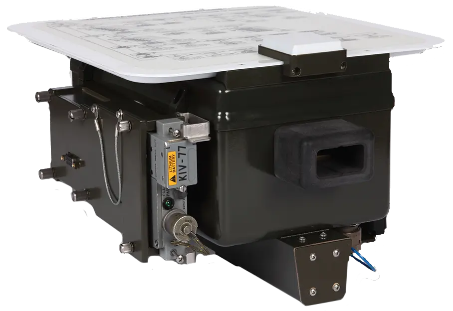
The APM-424(V)5 supports both DoD AIMS 04-900A Option A (KIV-78) and Option B (KIV-77) crypto appliqués through interchangeable side-mounted housings, and also supports KIR-1A/1C, KIT-1A/1C and KIV-6 with the appropriate cable or adapter. An internal GPS receiver synchronizes the real-time clock to UTC.
The test set is hand-held and battery powered, with one-piece, 3-button Go/No-Go operation and self-diagnostics. Parametric test results can be stored and downloaded to a PC for review or maintenance logging, and a Windows-based remote interface GUI is available.
The product is controlled for export under the International Traffic in Arms Regulations (ITAR).
Key Features
- Certified to DoD AIMS 17-1000
- Supports DoD AIMS 04-900A Option A (KIV-78) and Option B (KIV-77) crypto appliqués, plus SIT-2010
- Transponder test modes 1, 2, 3/A, C, S (EHS/ELS), 4, Mode 5 (Level 1 and 2)
- Interrogator test modes 1, 2, 3/A, C, S, 4, Mode 5, TCAS, ETCAS (Level 1 and 2)
- DO-260B compliant; ADS-B Out test capability
- GPS time/date acquisition via GPS antenna, crypto or manually
- Hand-held and battery powered
- One piece, 3-button point and shoot Go/No-Go operation
- Self-diagnostic
- Parametric test results can be stored for downloading to a PC
- NSN: 6625-01-583-2774 (APM-424(V)5 w/ KIV-77 adapter)
Specifications
| Displays | Internal: 20 character by 4 line alphanumeric OLED, 0.197” character height with green Accept, red Reject, and battery status indicators |
|---|---|
| Controls | 3 buttons: test sequence advance, test sequence repeat, and test result data |
| Remote | Windows Based Remote Interface GUI |
| Test Range | 10 to 150 ft |
|---|---|
| Modes 1, 2, 3A | Display code, identification, and emergency status |
| Mode C | Displays altitude |
| Mode 4 |
Stand alone operation, but must be filled with challenge video patterns from COMSEC, displays code A or B and verification bit status
Requires KIR or KIV with adapter to operate
|
| Mode 5 |
Housing for 04-900A Option A and B; Interrogates with Mode 5 Level 1 Formats 0-9 and Mode 5 Level 2 Formats 16-23, decodes and displays reply/report data
Requires Mode 5 crypto appliqué to operate
|
| Mode S |
Interrogates with: UF0, UF11 (all call), UF4 (altitude), UF5 (identity), UF4 asking for DF20 (altitude), UF5 asking for DF21 (identity), containing Datalink capability report, DF16 (long TCAS surveillance)
Decodes and displays Mode S ELS and EHS DAP’s (BDS 1,0; 1,7; 1,8-1,C; 2,0; 3,0; 4,0; 5,0; 6,0)
|
| ADS-B | DO-260B compliant, ADS-B Out |
| Test Range | 30 to 200 ft |
|---|---|
| Static Target Mode 1 | Responds with 1200 |
| Static Target Mode 2 | Responds with 1202 |
| Static Target Mode 3/A | Responds with 1203 (4096 code) |
| Static Target Mode C | Responds with configurable altitude |
| Static Target Mode 4 | Requires Mode 4 crypto appliqué to operate |
| Static Target Mode 5 |
Replies to Mode 5 Level 1 Formats 0-9 and Level 2 Formats 16-23
Requires Mode 5 crypto appliqué to operate
|
| Static Target Mode S | Replies to: UF11 (all call), UF0 (short TCAS surveillance), UF16 (long TCAS surveillance), UF4 (altitude), UF5 (Identity), UF20 (long altitude), UF21 (long identity) |
| Dynamic Target Scenarios |
Level, Above (2000 ft above configured altitude), Dive (from 5000 ft above), Climb (from 5000 ft below)
Intruder starts at 15 nmi distance UUT, ends at approximately 0 nmi; closing speed fixed at 720 knots; configured altitude is 0-20,000 ft
|
| Target Simulation – Multiple | 4, 8, 16, 32, 64, 128 and 256 nmi |
| Target Simulation – Single | 4 nmi, IDENT On/Off, EMERG On/Off, pilotless |
| Target Simulation – Group | 12 targets 2 nmi apart, starting at 4 nmi |
| Antenna Type | End-fire antenna with sum and difference feeds |
|---|---|
| Interrogation Beamwidth | Approximately ±5 degrees |
| Polarization | Vertical |
| Direct Port Impedance | 50 Ω |
| Direct Port SWR | 1.3:1 max |
| Direct Port Connector |
TNC
All over-the-air and direct connection port testing use identical test criteria
|
| Operating Modes | Unit operates either from external DC input power or internal batteries |
|---|---|
| External DC Input | 11.5 to 28 V DC input, 25 W max. |
| Surge Protection | MIL-STD-704E figure 9 (50 volts peak for 12.5 ms, then reducing linearly to 29 V over 70 ms) |
| Reverse Polarity | -30 volts max. |
| Battery Compatibility |
NiCAD re-chargeable battery assy, 7.2 volt DC nominal; compatible with commercial ‘C’ NiCAD, NiMH or alkaline batteries
Replaceable internal batteries, disassembly of unit is not required; reverse polarity protected
|
| Internal Battery Charger |
Full re-charge time within 8 hours from fully discharged state
Operates from external DC input; charge restricted to 0 to +40°C nominal battery temperature; battery will charge with unit operating unless an external COMSEC is connected
|
| Discharge Protection | Test set automatically shuts off to prevent excessive battery discharge |
| Generator Frequency | 1030 or 1090 ±0.01 MHz |
|---|---|
| Generator Power (antenna) |
+4 to -44 dBm, 1 dB resolution, ±1.5 dB accuracy at antenna connector
±2 dB radiated antenna field strength
|
| Generator Power (direct port) | -40 to -88 dBm, 1 dB resolution, ±1.5 dB accuracy at direct port |
| Pulse Shape and Timing | Modes 3/A, C, S comply with RTCA/DO-181D, Modes 1, 2, 4, 5 comply with NATO STANAG 4193 Part V & DOD AIMS 03-1000A |
| ISLS Amplitude | Equal to P1 on difference or sum ports when enabled |
| Interrogation Rate (transponder test mode) | Modes 1,2,3/A,C,4,5: 235 ±5 Hz; Mode S: 50 ±5 Hz |
| Harmonics | 2nd and 3rd harmonic >30 dBc |
| Spurious |
-50 dBm max. in standby; 50 dBc or -50 dBm max. in transmit when measured at the antenna connection
Applies at greater than 60 MHz from TX center frequency
|
| Frequency Range | 1090 or 1030 MHz |
|---|---|
| Amplitude Range | +68 to +20 dBm at direct port, +24 to -24 dBm at antenna port |
| Input Protection | 1 μs pulse width, 1% max duty cycle; Direct Input +68 dBm; Antenna Input +30 dBm at antenna connection |
| Power |
1 dB resolution, ±1.5 dB accuracy at antenna port, ±1.5 dB at direct port, ±2 dB antenna field strength
Peak power of pulse obtained using 100 ns averaging period; within ±5 MHz of nominal for specified accuracy
|
| Frequency |
0.01 MHz resolution ±0.10 MHz accuracy with >400 ns pulse width (transponder mode); ±0.05 MHz accuracy with >750 ns pulse width (interrogator mode)
Average frequency between 90% points
|
| Pulse Spacing | ±25 ns measured between leading edges for pulses with rise times <100 ns |
| Pulse Width | ±25 ns for pulses with rise times of 50 to 100 ns, fall times of 50 to 200 ns |
| Receiver Bandwidth | >10 MHz at 3 dB points |
| Oscillator Leakage | -50 dBm max. at antenna connection |
| Image Rejection | >40 dBc |
| Appliqué Housing/Interface | Interchangeable side mounted housings: 04-900A Option A (KIV-78/KIV-6/QRTK6 NG Adapter); 04-900A Option B (KIV-77/SIT-2010 Adapter) |
|---|---|
| Circular Connector Interface | Supports KIR-1A/1C, KIT-1A/1C and KIV-6 with appropriate cable or adapter |
| Power for COMSEC |
KIT-1A/KIR-1A: External 115 VAC provided through KIT/KIR-1A interface cable; KIT-1C/KIR-1C: 22 to 29 VDC at 3 W max.; KIV-6: 15 ±0.75 VDC at 200 mA max.; KIV-77: +5 VDC, 2.2 W; KIV-78: 15 ±1.0 VDC at 200 mA max.
Except KIT-1A/KIR-1A, power provided by the test set
|
| Timekeeping | Internal Real Time Clock, ±3.5 ppm accuracy; Internal GPS receiver for UTC synchronization of Real Time Clock |
| Reply Code | M1/M2/M3A: 4096 code; MC: Altitude in ft; MS: 4096 code; M5 (M1/M2/M3A/MC): 4096 code |
|---|---|
| Receiver Sensitivity (Transponder) | Displays MTL in dBm |
| Receiver Sensitivity (Interrogator) | Tests MDL margin 0 to -12 dB |
| Squitter | M5: Level 2 squitter period (ms); MS: DF11 Acquisition (sec) |
| Angle Reflection | Indicates unacceptable levels of multi-path interference |
| Umbilical Testing | Connector provided for direct connection to transponder |
| Mode S Testing |
Supports the RF link portion of the installed equipment performance requirements of DO-181D and ED-73A. Decodes and displays ELS and EHS data
Additional equipment is required to simulate aircraft pressure altitude for the altitude reporting verification
|
| Mode 5 Testing | Indicates correct reply format as defined in NATO STANAG 4193 Part V and AIMS 03-1000A. Decodes, displays Level 1 ID & DATA reply types and Level 2 PIN, M1/M2 & M3/Altitude report types |
| Size (Test Set Only) | 7.5”H x 11.5”W x 14.1”D (19.05 cm x 29.21 cm x 35.81 cm) |
|---|---|
| Size (with Transit Case) | 20.4”H x 31.3”W x 15.5”D (51.82 cm x 79.50 cm x 39.37 cm) |
| Weight | 12.25 lbs. (test set with battery) |
| Shipping Weight | 50 lbs. (22.7kg) |
| Transit Case | Watertight sealed enclosure with pressure release valve; Empty 16 lbs (7.3 kg), Full 41 lb (18.6 kg) |
| Standard | MIL-PRF-28800, Class 1 |
|---|---|
| Operational Temperature | -40° to + 55°C (-40° to + 131° F) |
| Storage Temperature | -55° to + 85°C (-67° to + 185° F) |
| Relative Humidity | To 100% for at least 6 hours |
| Splash Proof | Rain at 1.8 inches per hour and the wind velocity is at least 20 miles per hour (mph), for a period of no less than 60 minutes |
| Altitude | 4,600 meters operating, 50,000 ft storage |
| Shock | Transit: 36 inch drop in transit case; High Impact: 36 inch drop; Functional: 30 G 11 ms half sine |
| Random Vibration | 10 Hz to 2000 Hz/60 mins per axis |
| EMI/RFI |
MIL-STD-461E (CE101, CE102, CS101, CS114, CS115, CS116, RE101, RE102, RE103, RS101, RS103)
RS103 Electric 2 MHz to 18 GHz, 50 V/m; does not apply within 10% of RX and TX operating frequency
|
| AC Power Adapter |
100 to 240 VAC ±10%, 47 to 63 Hz input; +12 V DC nominal, 5.0 ADC nominal output
APM-424(V)4 datasheet lists 2.0 ADC nominal output current; value from APM-424(V)5 datasheet used
|
|---|---|
| External Battery Charger |
Charges or discharges one battery stick; 3 hours max. for 3 AH battery
Dependent on battery charge state
|
| RF Direct Connect Cable | 12 ft (3.6 m); TNC male right angle, TNC male straight; TNC female to N male adapter included |
| Battery Stick | High capacity rapid charge NiCad, 7.2 V DC nominal, 3 amp hour at +25°C (77°F) nominal |
| Option A (KIV-78/KIV-6/QRTK6 NG Adapter) |
Length 8.85 in (22.48 cm), Height 4.49 in (11.40 cm), Width 2.93 in (7.44 cm); 2 lb (0.91 kg max.)
Attaches to the 78 pin D sub female crypto interface adapter
|
| Option B (KIV-77/SIT-2010 Adapter) |
Length 7.75 in (19.68 cm), Height 4.2 in (10.67 cm), Width 1.76 in (4.47 cm); 1 lb (0.45 kg max.)
Attaches to the 78 pin D sub female crypto interface adapter
|
| Bench Utility Software | Allows download, viewing, and saving test data from test set; Microsoft Windows 95, 98, 2000, XP, NT 4.x; CD ROM |
Specifications are taken from the manufacturer's documentation. See the datasheet for complete and current values.
Applications
- Mode 5 TX/RX pulse measurement
- Mode 5 squitter data
- Mode 5 data acquisition formats 0-23
- TS-4542 shipboard interrogator testing
- ADS-B Out testing
- KIV-77 and SIT-2010 support
- KIV-78 support
- Flight line transponder and interrogator testing
Options & Accessories
| Option | Description |
|---|---|
| 04-900A Option A | KIV-78/KIV-6/QRTK6 NG Adapter — Side-mounted crypto appliqué housing; attaches to the 78 pin D sub female crypto interface adapter |
| 04-900A Option B | KIV-77/SIT-2010 Adapter — Side-mounted crypto appliqué housing; attaches to the 78 pin D sub female crypto interface adapter |
| 86738 | Kit, upgrade TS-4530 or APM-424(V)3 to APM-424(V)5 — Factory upgrade kit for existing units; COMSEC adapters sold separately |
| 88573 | Kit, upgrade APM-424(V)4 to APM-424(V)5 — Factory upgrade kit for existing units; COMSEC adapters sold separately |
| 88572 | Kit, upgrade TS-4530-1 to APM-424(V)5 — Factory upgrade kit for existing units; COMSEC adapters sold separately |
Documents & Resources
Related Products
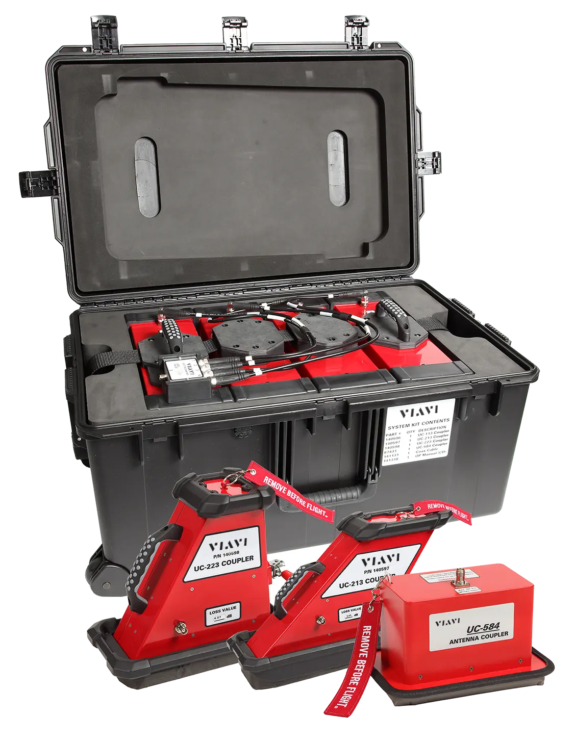
Antenna coupler kit for isolated F-16 IFF interrogator and transponder radiated power and minimum trigger level testing on the ramp.
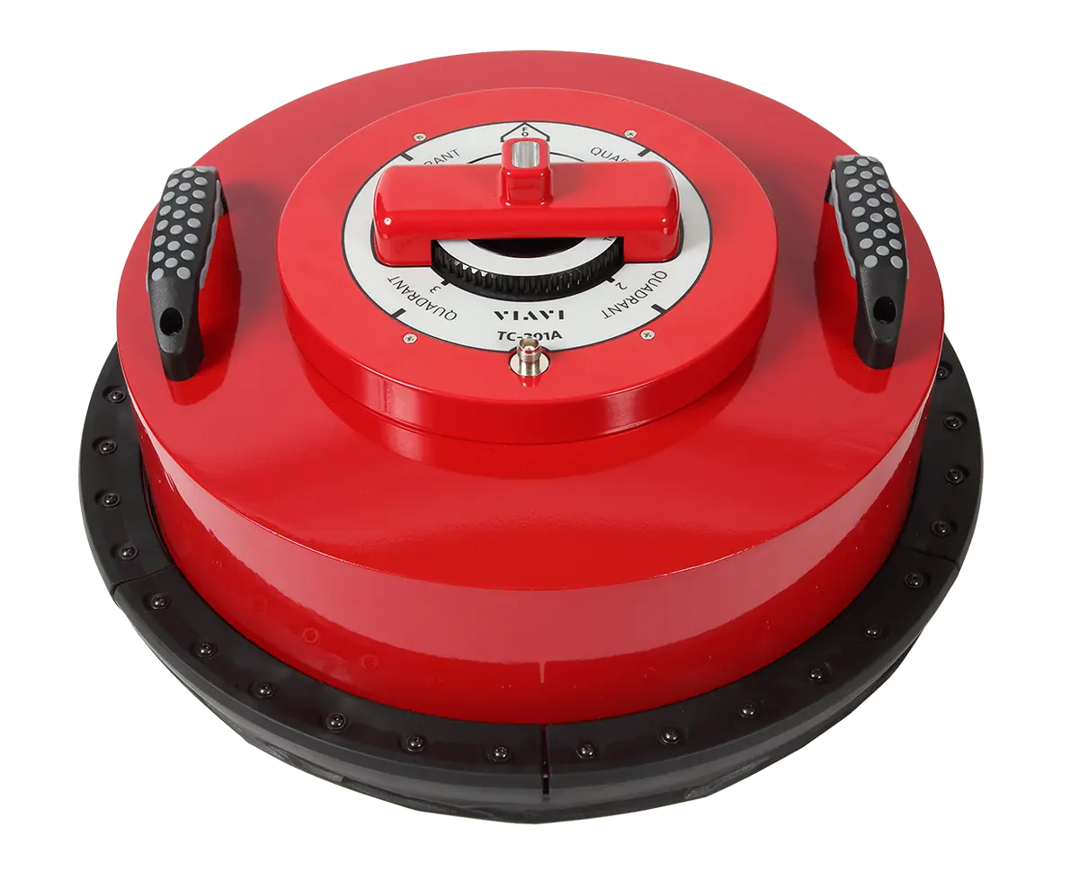
Combined TCAS and transponder directional antenna couplers that shield the RF signal during avionics flight line testing.