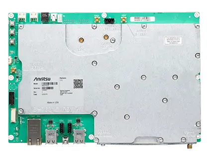
Anritsu MS27100A Spectrum Monitor Module, 9 kHz to 6 GHz Remote RF Signal Monitoring
Compact OEM spectrum monitor module, 9 kHz to 6 GHz, for remote RF interference detection and spectrum occupancy monitoring.
- External Power
- 11.0 to 14.5 VDC, 11 W, 5.5 mm Barrel Connector
- 10 MHz Reference Output
- MCX(f)
- IF Output
- MCX(f)
- IF Output Frequency
- 140 MHz
Overview
The Anritsu MS27100A is a spectrum monitor module covering 9 kHz to 6 GHz, designed for OEM solutions that monitor the radio spectrum and geo-locate signals of interest. Its small form factor allows it to be placed in rack-mount systems or enclosures where space is limited, or integrated and branded into a user's own enclosure.
By monitoring the spectrum continuously, the MS27100A helps identify illegal or unlicensed interference signals as they occur. Patterns of unwanted signal activity can be examined to characterize and locate the source of interference. The module is also used to characterize spectrum occupancy, giving regulators and operators the data needed to assess band usage, and to support enforcement of spectrum regulations for services such as police, fire, air traffic control, military and emergency communications.
Remote deployment
The module has a single RF input port, Gigabit Ethernet for remote control and USB ports for accessories. It can be expanded to six RF inputs with the optional 2000-1894-R multiplexer. An integrated web server allows measurements to be viewed and controlled from a browser, and SCPI commands are supported for remote control. A watchdog timer, remote power cycling, automated recovery and remote firmware updates support long-term unattended operation. An IF output (140 MHz) is available for further processing.
Software and geolocation
IQ data can be captured in block or streaming mode and is time-stamped using the integrated GPS receiver, enabling Time Difference of Arrival (TDOA) techniques. The optional Vision MX280001A software provides automated spectrum monitoring, alarms and signal geolocation using three or more probes, and the IQ Signal Master MX280005A software provides post-processing and vector signal analysis of captured IQ data.
Key Features
- 9 kHz to 6 GHz frequency range
- Sweep speed up to 24 GHz/s
- Integrated web server to view, control and conduct measurements via web browser (Chrome or Firefox)
- Remote firmware updates
- Watchdog timer for long-term stability of remotely deployed monitors
- Low spurious levels for accurate signal discovery
- 20 MHz instantaneous FFT bandwidth
- Low power consumption <11 watts
- Integrated GPS receiver for location and time synchronization
- Gigabit Ethernet
- Measurements: occupied bandwidth, channel power
- Interference analysis: spectrogram and signal strength
- IQ block mode and streaming with time stamping for TDOA applications
- Remote control via SCPI commands
- Expandable to six RF input ports with optional multiplexer
- Optional Vision software for automated measurements, alarms and geo-locating signal sources
- AeroShield drone detection and tracking
- 140 MHz IF output
Specifications
| External Power | 11.0 to 14.5 VDC, 11 W, 5.5 mm Barrel Connector |
|---|---|
| 10 MHz Reference Output | MCX(f) |
| IF Output | MCX(f) |
| IF Output Frequency | 140 MHz |
| GPS Antenna Input | MCX(f) |
| 10 MHz Reference Input | +10 dBm max, +5 VDC max, MCX(f) |
| Ethernet | Gbit Ethernet, RJ45 connector |
| USB | USB Type A (4) |
| RF Input | SMA(f), 50Ω |
| RF In Damage Level |
+30 dBm peak, ±50 VDC maximum continuous input
≥ 10 dB attenuation, > 100 MHz
|
| Frequency Range | 9 kHz to 6 GHz (tunable to 0 Hz) |
|---|---|
| Frequency Span | 10 Hz to 6 GHz |
| Tuning Resolution | 1 Hz |
| Frequency Reference Accuracy | ±1.5 ppm (25 °C ± 25 °C) |
| Frequency Reference Aging | ±1.0 ppm/year aging |
| Frequency Reference Accuracy with GPS | < ±50 ppb with GPS on |
| Sweep Speed, 10 kHz RBW |
5 GHz/s
Typical, full span FFT mode
|
| Sweep Speed, 30 kHz RBW |
12 GHz/s
Typical, full span FFT mode
|
| Sweep Speed, 3 MHz RBW |
24 GHz/s
Typical, full span FFT mode
|
| Resolution Bandwidth (RBW) |
10 Hz to 3 MHz in 1–3 sequence
–3 dB bandwidth
|
|---|---|
| Video Bandwidth (VBW) |
10 Hz to 3 MHz in 1–3 sequence (auto or manually selectable)
–3 dB bandwidth
|
| SSB Phase Noise @ 1 GHz, 10 kHz offset |
(–98 dBc/Hz)
Typical
|
|---|---|
| SSB Phase Noise @ 1 GHz, 100 kHz offset |
(–98 dBc/Hz)
Typical
|
| Dynamic Range |
(> 106 dB) (2.4 GHz)
2/3 (TOI-DANL) in 1 Hz RBW; typical
|
|---|---|
| Measurement Range | DANL to Maximum Continuous Input |
| Reference Level Range | –150 dBm to +30 dBm |
| Attenuator Range | 0 dB to 50 dB in 5 dB steps |
| Amplitude Units | Log Scale Modes: dBm, dBµV |
| Amplitude Accuracy, 9 kHz to 100 kHz |
± 2.5 dB
Attenuation ≤ 40 dB, preamp off for frequencies less than 100 kHz
|
| Amplitude Accuracy, > 100 kHz to 6 GHz |
± 1.5 dB
Attenuation ≤ 40 dB; Quick Fact Sheet lists ±2.5 dB without frequency split
|
| VSWR | < 2.5:1 typical |
| 10 MHz to 3.3 GHz, preamp off |
–145 dBm max, –150 dBm typical
RBW normalized to 1 Hz, 0 dB attenuation, reference level –20 dBm
|
|---|---|
| > 3.3 GHz to 4.1 GHz, preamp off |
–140 dBm max, –145 dBm typical
RBW normalized to 1 Hz, 0 dB attenuation, reference level –20 dBm
|
| > 4.1 GHz to 5 GHz, preamp off |
–138 dBm max, –143 dBm typical
RBW normalized to 1 Hz, 0 dB attenuation, reference level –20 dBm
|
| > 5 GHz to 6 GHz, preamp off |
–128 dBm max, –136 dBm typical
RBW normalized to 1 Hz, 0 dB attenuation, reference level –20 dBm
|
| 10 MHz to 3.3 GHz, preamp on |
–162 dBm max, –165 dBm typical
RBW normalized to 1 Hz, 0 dB attenuation, reference level –50 dBm
|
| > 3.3 GHz to 4.1 GHz, preamp on |
–159 dBm max, –162 dBm typical
RBW normalized to 1 Hz, 0 dB attenuation, reference level –50 dBm
|
| > 4.1 GHz to 5 GHz, preamp on |
–156 dBm max, –160 dBm typical
RBW normalized to 1 Hz, 0 dB attenuation, reference level –50 dBm
|
| > 5 GHz to 6 GHz, preamp on |
–146 dBm max, –154 dBm typical
RBW normalized to 1 Hz, 0 dB attenuation, reference level –50 dBm
|
| Residual Spurious, preamp off, > 10 MHz |
(< –80 dBm)
Typical; RF input terminated, 0 dB input attenuation
|
|---|---|
| Residual Spurious, preamp on, > 10 MHz |
(< –95 dBm)
Typical; RF input terminated, 0 dB input attenuation
|
| Residual Spurious, preamp on, 16 MHz to 18 MHz |
(< –88 dBm)
Typical; RF input terminated, 0 dB input attenuation
|
| Input-Related Spurious |
< –60 dBc
0 dB attenuation, –30 dBm input, carrier offset > 5 MHz
|
| Input-Related Spurious Exceptions | < –60 dBc, input = 4140 MHz |
| Second Harmonic Distortion, 50 MHz |
(–50 dBc)
Typical; 0 dB attenuation, –30 dBm input
|
| Second Harmonic Distortion, > 50 MHz to 200 MHz |
< –60 dBc
Typical; 0 dB attenuation, –30 dBm input
|
| Second Harmonic Distortion, > 200 MHz to 3000 MHz |
< –60 dBc
Typical; 0 dB attenuation, –30 dBm input
|
| Third-Order Intercept (TOI), 800 MHz |
(+7 dBm)
Typical; preamp off, –20 dBm tones 100 kHz apart, 0 dB attenuation, reference level –20 dBm
|
| Third-Order Intercept (TOI), 2400 MHz |
(+17 dBm)
Typical; preamp off, –20 dBm tones 100 kHz apart, 0 dB attenuation, reference level –20 dBm
|
| Third-Order Intercept (TOI), 200 to 2200 MHz |
+10 dBm
Preamp off, –20 dBm tones 100 kHz apart, 0 dB attenuation, reference level –20 dBm
|
| Third-Order Intercept (TOI), > 2.2 GHz to 5.0 GHz |
+8 dBm
Preamp off, –20 dBm tones 100 kHz apart, 0 dB attenuation, reference level –20 dBm
|
| Third-Order Intercept (TOI), > 5.0 GHz to 6.0 GHz |
+14 dBm
Preamp off, –20 dBm tones 100 kHz apart, 0 dB attenuation, reference level –20 dBm
|
|
100 MHz to 6 GHz, ≥ 10 dB attenuation
without Option 406
|
+30 dBm, ±50 VDC
RF input to MS27100A; for lower frequencies, derate maximum continuous input by 6 dB per decade
|
|---|---|
|
300 kHz to 6 GHz, < 10 dB attenuation
without Option 406
|
+10 dBm, ±50 VDC
RF input to MS27100A; for lower frequencies, derate maximum continuous input by 6 dB per decade
|
|
9 kHz to 6 GHz, preamp on
without Option 406
|
–10 dBm, ±50 VDC
RF input to MS27100A
|
|
100 MHz to 6 GHz, ≥ 10 dB attenuation
MS27100A-0406
|
+20 dBm, ±50 VDC
RF input to multiplexer; for lower frequencies, derate maximum continuous input by 4 dB per decade
|
|
300 kHz to 6 GHz, < 10 dB attenuation
MS27100A-0406
|
+10 dBm, ±50 VDC
RF input to multiplexer; for lower frequencies, derate maximum continuous input by 4 dB per decade
|
|
9 kHz to 6 GHz, preamp on
MS27100A-0406
|
–10 dBm, ±50 VDC
RF input to multiplexer
|
| Data Types, I/Q time series | 8, 10, 16 or 24 bit resolution |
|---|---|
| Data Types, spectrum trace | 100 to 4000 points |
| Data Transfer Modes | I/Q time series or spectrum trace in streaming or block mode |
| I/Q Data Streaming Rate | Gapless on 100Base-T network, Up to 2.6 MHz signal bandwidth |
| I/Q Data Time Stamp Resolution | 8.7 ns |
| I/Q Recording Time, 20 MHz signal bandwidth |
1.3 s (24 bits), 2.5 s (16 bits), 3.8 s (10 bits), 5 s (8 bits)
Typical; output data rate 76.25 / 3 MSPS
|
| I/Q Recording Time, 2.67 MHz signal bandwidth |
8.4 s (24 bits), 16.8 s (16 bits), 25.2 s (10 bits), 33.6 s (8 bits)
Typical; output data rate 76.25 / 20 MSPS
|
| I/Q Recording Time, 267 kHz signal bandwidth |
1.4 min (24 bits), 2.8 min (16 bits), 4.2 min (10 bits), 5.6 min (8 bits)
Typical; output data rate 76.25 / 200 MSPS
|
| I/Q Recording Time, 1.33 kHz signal bandwidth |
4.66 h (24 bits), 9.33 h (16 bits), 13.99 h (10 bits), 18.65 h (8 bits)
Typical; output data rate 76.25 / 40000 MSPS
|
| System Status | Temperature, Serial Number, Firmware Version, Options Installed, Self Test, Application Self Test, GPS |
|---|---|
| Internal Trace/Setup Memory | 4 GB internal memory available for storing files |
| Power Consumption | <11 watts |
| Warranty | Standard three-year warranty |
| Operating Temperature Range |
0 ºC to 50 ºC
Quick Fact Sheet lists -40 ºC to 50 ºC; technical data sheet value used
|
|---|---|
| Storage Temperature Range | –40 ºC to 71 ºC |
| Maximum Relative Humidity | 95 % RH at 30 ºC, non-condensing |
| Vibration, Sinusoidal | 5 Hz to 55 Hz |
| Vibration, Random | 10 Hz to 500 Hz |
| Half Sine Shock | 30 gn |
| Altitude | 4600 meters, operating and non-operating |
| Explosive Atmosphere | MIL-PRF-28800F, Section 4.5.6.3; MIL-STD-810G, Method 511.5, Procedure 1 |
| ESD, RF Input Pin | Withstands up to ±4 kV |
| Weight | 0.93 kg (2.05 lb) without packaging |
|---|---|
| Size | 165.36 x 244.00 x 27.75 (mm) |
|
Frequency
2000-1894-R
|
9 kHz to 6 GHz
All specifications typical
|
|---|---|
|
Insertion Loss
2000-1894-R
|
2 dB at 1 GHz, 5 dB at 6 GHz
Typical
|
|
Antenna Port Isolation
2000-1894-R
|
> 40 dB < 3 GHz, > 30 dB ≥ 3 GHz
Typical
|
|
DC Power
2000-1894-R
|
5 VDC via USB |
|
Weight
2000-1894-R
|
0.18 kg (0.40 lb) |
|
RF Antenna Inputs
2000-1894-R
|
SMA(f) (x6) |
|
RF Output
2000-1894-R
|
SMA(f) (connects to MS27100A RF In, RF cable NOT included) |
Specifications are taken from the manufacturer's documentation. See the datasheet for complete and current values.
Applications
- Detection of illegal or unlicensed AM/FM/cellular broadcasts
- Sensitive site monitoring (national borders, military facilities, nuclear power plants)
- Airport monitoring
- Monitoring jails and prisons for illegal broadcasts
- Positive Train Control (PTC) communication channel monitoring
- Cable TV leakage monitoring
- Government enforcement of spectrum policies
- Spectrum occupancy characterization
- White space analysis
- Signal coverage monitoring
Included
- 40-187-R AC/DC Power Supply, 1 m, 12 VDC Output
Options & Accessories
| Option | Description |
|---|---|
| MS27100A-0706 | 9 kHz to 6 GHz Frequency Range — The MS27100A requires one frequency option |
| MS27100A-0128 | Vector Signal Analysis Enabled (use with MX280005A) — Listed on the web page as MS27102A-0128; technical data sheet code used |
| MS27100A-0406 | Enables USB Interface to 6-port RF multiplexer (requires 2000-1894-R) |
| MS27100A-0400 | Vision Monitor Enabled |
| MS27100A-0401 | Vision Locate Enabled (requires Option 400) |
| MS27100A-0407 | Vision High-Speed Port Scanner Enabled |
| MS27100A-0486 | Vision Coverage Mapping (requires Option 407) |
| MS27100A-0098 | Standard Calibration to ISO17025 and ANSI/NCSL Z540-1 — Includes calibration certificate |
| MS27100A-0099 | Premium Calibration to ISO17025 and ANSI/NCSL Z540-1 — Includes calibration certificate, test report, and uncertainty data |
| 2000-1894-R | 6-Port RF Multiplexer — Optional six-to-one multiplexer controlled via a USB-A to 5-pin connection; switch insertion loss correction is linked to the MS27100A through this USB interface (requires Option 406) |
| 3-67367 | USB-A to HC5 5-pin header cable, 30 cm — Requires software Option 406 |
Documents & Resources
Related Products
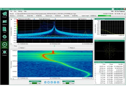
PC software for capturing, playing back, converting and analyzing IQ data from Anritsu spectrum analyzers, with modulation quality measurements.
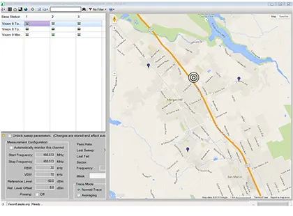
Windows PC software for monitoring, identifying and geo-locating interference signals with networks of Anritsu remote spectrum monitors.