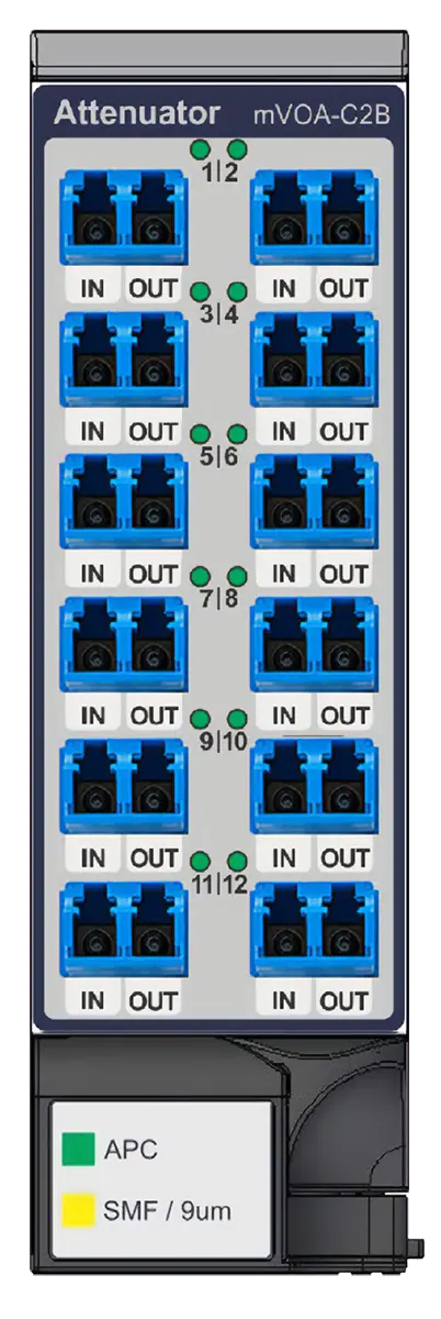
MAP Series mVOA-C2B MVOA-C2B12-SB0-M100-MLU 12-Channel Variable Optical Attenuator, LC/APC
MEMS-based MAP Series attenuator module with 12 independent variable optical attenuators, no power monitors, SMF LC/APC connectors.
- Number of Channels
- 12
- Power Monitors
- No Monitor
- Connector
- SMF LC/APC
Overview
The VIAVI MVOA-C2B12-SB0-M100-MLU is a configuration of the MAP Series mVOA-C2B high-density variable optical attenuator module. This version has 12 attenuator devices, no input/output power monitors, and singlemode fiber LC/APC connectors.
The mVOA-C2B uses a MEMS mirror design. It offers low insertion loss, low return loss and low polarization dependent loss, with good repeatability, accuracy and long-term stability. It succeeds the mVOA-C1 and covers a wide wavelength range. Typical uses include client optic testing, next-generation coherent interfaces, long-haul network stress testing and silicon photonics development.
The module is a hot-pluggable, single-slot cassette for MAP-300 generation mainframes. A 3U MAP-300 mainframe holds up to eight modules, for up to 96 independently controlled attenuators. This suits network emulation test systems in lab and production environments.
Operating mode
The no-monitor variant runs in Attenuator Mode. In this mode the user sets the output attenuation directly, either from the user interface or with remote SCPI commands. Constant Power Mode and IL Mode need the in/out monitor variant.
Key Features
- MEMS mirror-based variable optical attenuation
- 12 independently controlled attenuators in a single-slot module
- Up to 96 attenuators in a single 3U MAP-300 mainframe
- Low insertion loss to minimize loss budget utilization
- High accuracy and repeatability to reduce measurement uncertainty
- Fast transition speed and settling time to reduce testing time
- Flat spectral response for CWDM and DWDM applications
- Low backreflection to reduce instabilities due to reflected light
- High input power capability for EDFA testing and multi-wavelength applications
- Hot-pluggable module for all MAP-300 generation mainframes
- Attenuation control from the UI or remote SCPI commands
Specifications
| Number of Channels |
12
Series offered with 4, 8 or 12 channels
|
|---|---|
| Power Monitors | No Monitor |
| Connector |
SMF LC/APC
Series offered with LC/PC and LC/APC
|
| Wavelength Range | 1260 to 1640 nm |
|---|---|
| Insertion Loss |
<=1.6 dB
No Monitor configuration
|
| Attenuation Range | > 40 dB |
| Return Loss | 40 dB min/55 dB typ |
| Shutter Isolation | > 45 dB |
| Maximum Optical Input Power |
27 dBm
No Monitor configuration
|
| Repeatability | ±0.05 dB (typ.), 0 dB to 30 dB |
|---|---|
| Repeatability | ±0.10 dB (typ.), 30 dB to 40 dB |
| Relative Attenuation Accuracy |
±0.15 dB (typ.), 0 dB to 10 dB; ±0.15 dB (typ.), 10 dB to 20 dB; ±0.20 dB (typ.), 10 dB to 20 dB
As printed in the datasheet; two entries list the same 10 dB to 20 dB range
|
| PDL | < 0.15 dB, at 0 dB |
| PDL | < 0.30 dB, 0 dB to 10 dB |
| PDL | < 0.50 dB, 10 dB to 20 dB |
| Attenuation Speed | 0.1 dB/s to 1000 dB/s |
|---|---|
| MAP Command Latency | < 1 ms |
| Activation Latency | < 500 μs |
| Trigger Latency | < 10 μs |
| Warm-up Time |
30 min
All optical measurements taken after minimum 30-minute warm up; measured at constant temperature of 23 ±5°C
|
|---|---|
| Slot Width | 1 standard module |
| Calibration Period | 1 Year |
| Operating Temperature |
10 °C to 40 °C
Requirement
|
| Storage Temperature | -30°C to 60°C |
Specifications are taken from the manufacturer's documentation. See the datasheet for complete and current values.
Applications
- Network emulation test systems
- Client optic testing
- Next-generation coherent interface testing
- Long-haul network stress testing
- Silicon photonics development
- EDFA testing
- CWDM and DWDM applications
- Lab and production test