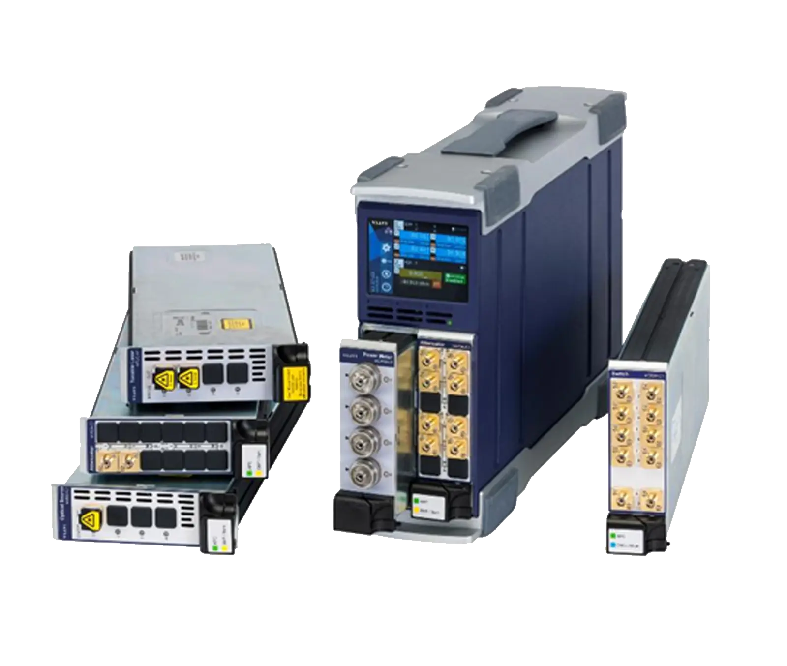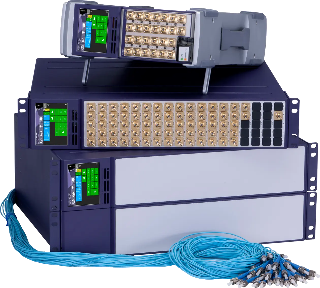
VIAVI MAP mOSW-C1 Optical Switch Module for MAP-200/MAP-300 Chassis
Plug-in optical switch module for VIAVI MAP chassis, in 1x2 to 1x64 single-mode and multimode configurations for test automation.
- Wavelength range, single-mode (SM)
- 1250 to 1650 nm
- Wavelength range, multimode (MM)
- 760 to 1360 nm
- Wavelength range, PM 1550 nm
- 1440 to 1650 nm
- Wavelength range, PM 1310 nm
- 1270 to 1650 nm
Overview
The VIAVI mOSW-C1 Optical Switch Module is a plug-in module for the MAP (Multiple Application Platform) series. It is part of the LightDirect module family and is built on the fourth-generation instrumentation class of VIAVI optical switch technology. It is designed for manufacturing test automation, where optical switches route signals between test instruments and devices under test.
The module brings the performance and repeatability of VIAVI's fixed-format 19-inch rack-mount switch systems to a modular plug-in format. According to VIAVI, the mOSW-C1 can reduce the size of switching systems by up to 75% and switches 50% faster than earlier designs. Switches are not cascaded to build larger channel counts, so insertion loss, PDL and repeatability stay the same regardless of switch size.
Configurations
The mOSW-C1 is optimized for 1x2, 2x2 and smaller channel counts up to 1x24. Pigtail versions are available up to 64 outputs. It supports single common input (1C), duplex (2D), dual parallel input (2E) and 2x2 crossover (2X) switch types. A module can hold one, two, four or eight independent switches. Single-width and dual-width modules are available, with bulkhead connectors or 2 m pigtails. A single part number defines each configuration, including the switch count, switch type, number of outputs, termination, options, fiber type and connector type.
Fiber types and options
The module is available for single-mode fiber, for OM1 and OM3 multimode fiber and for 100 µm fiber. Polarization-maintaining fiber versions are available for 1310 and 1550 nm. Its expanded-beam design makes the multimode versions modally transparent, which preserves IEC-specified launch conditions. The optional Power Trim (PTRIM) adds a bidirectional in-line power monitor on the common port and up to 20 dB of programmable loss on the connected path. A High Directivity option is available for certain single-mode 1x2 and 2x2 types.
Control and compatibility
The mOSW-C1 runs in MAP-200 and MAP-300 chassis, including the MAP-220C, MAP-230B, MAP-280, MAP-330 and MAP-380. The switches can be controlled locally through the MAP GUI or remotely over VNC, Ethernet or GPIB. Remote control uses SCPI commands in either MAP-series style or the syntax of the VIAVI SB/SC series. The module is a drop-in replacement for the older mLCS modules.
Key Features
- Fourth-generation VIAVI optical switch technology in a plug-in MAP module
- All-optical switching, independent of data rate and transmission format
- Low loss for all configurations from 1x2 to 1x176 across the mOSW/mISW family
- 0.04 dB PDL and ±0.005 dB repeatability on single-input versions
- Switches are never cascaded; IL, PDL and repeatability are independent of switch size
- SCPI remote interface with MAP series commands or VIAVI SB/SC series backward compatibility
- Drop-in replacement for the older mLCS modules
- 1C, 2D (duplex), 2E (dual input) and 2X (2x2 crossover) input configurations
- Power Trim (PTRIM) option with bidirectional power monitor and up to 20 dB programmable loss
- Expanded beam technology makes multimode switches modally transparent
- Available for single-mode, OM1, OM3 multimode and 1310/1550 nm polarization-maintaining fiber
- Single-width and dual-width modules with bulkhead or 2 m pigtail termination
- Up to eight 1x2 switches in a single-slot module
- GUI with hover-and-release channel selection and a programmable connection table
- Specified settling time to 90% and 99% of final insertion loss
Specifications
| Wavelength range, single-mode (SM) |
1250 to 1650 nm
For IEC 60793-2-50 Type B1.3/ISO 11801 OS2 compliant fiber
|
|---|---|
| Wavelength range, multimode (MM) |
760 to 1360 nm
For OM1 and OM3 fiber compliant with ISO/IEC 11801
|
|
Wavelength range, PM 1550 nm
1C
|
1440 to 1650 nm |
|
Wavelength range, PM 1310 nm
1C
|
1270 to 1650 nm |
|
Insertion loss, single-mode
1C, 2D
|
0.7 dB
Excluding connectors; tested at 1310 and 1650 nm with IEC 62614-compliant EF
|
|
Insertion loss, single-mode
2E
|
0.9 dB
Excluding connectors
|
|
Insertion loss, multimode
1C, 2D
|
0.9 dB
Excluding connectors; tested at 850 and 1300 nm with IEC 62614-compliant EF
|
|
Insertion loss, multimode
2E
|
1.0 dB
Excluding connectors
|
|
Insertion loss, polarization maintaining
1C
|
0.9 dB |
|
Extinction ratio (PM), typical
1C
|
18 dB |
|
Extinction ratio (PM), minimum
1C
|
15 dB |
|
Return loss, single-mode
1C, 2D
|
62 dB
Excluding connectors, 2 m pigtail length; tested at 1310/1625 nm
|
|
Return loss, single-mode
2E
|
60 dB
Excluding connectors, 2 m pigtail length
|
|
Return loss, multimode OM1 (62.5 µm)
1C, 2D
|
30 dB
Tested at 850/1300 nm
|
|
Return loss, multimode OM1 (62.5 µm)
2E
|
25 dB |
|
Return loss, multimode OM3 (50 µm)
1C, 2D
|
40 dB
Tested at 850/1300 nm
|
|
Return loss, multimode OM3 (50 µm)
2E
|
35 dB |
|
Polarization-dependent loss (PDL)
1C
|
0.04 dB
Tested at 1310 and 1650 nm
|
|
Polarization-dependent loss (PDL)
2D
|
0.05 dB
Tested at 1310 and 1650 nm
|
|
Polarization-dependent loss (PDL)
2E
|
0.07 dB
Tested at 1310 and 1650 nm
|
|
Repeatability, sequential switching
1C
|
±0.005 dB
Measured between two consecutive readings over 100 cycles
|
|
Repeatability, sequential switching
2D, 2E
|
±0.01 dB
Measured between two consecutive readings over 100 cycles
|
|
Repeatability, random switching
1C
|
±0.025 dB |
|
Repeatability, random switching
2D, 2E
|
±0.04 dB |
| IL stability (maximum) |
±0.025 dB
Any channel drift relative to reference channel at ±3°C ambient deviation over 168 hours
|
| Crosstalk (maximum), single-mode | –80 dB |
| Crosstalk (maximum), multimode | –60 dB |
| Max input power (optical) | 300 mW |
| Lifetime | 100 million switching cycles |
| Electro-mechanical, break to make (SM/MM) |
20+10*(N–1) ms
≤ 24 ports
|
|---|---|
| Electro-mechanical, break to make (SM/MM) |
55+30*(N–1) ms
>24 ports < 72
|
| Electro-mechanical, break to make (PM) |
30+20*(N–1) ms
≤ 24 ports
|
| Settling time to 90% final IL |
60 ms
≤ 24 ports
|
| Settling time to 90% final IL |
70 ms
>24 ports < 72
|
| Settling time for 99% final IL |
90 ms
≤ 24 ports
|
| Settling time for 99% final IL |
120 ms
>24 ports < 72
|
|
Wavelength range, single-mode (SM)
1x2, 2x2
|
1290 to 1330 nm and 1520 to 1650 nm |
|---|---|
|
Wavelength range, multimode (MM)
1x2, 2x2
|
760 to 1360 nm |
|
Insertion loss, single-mode
1x2
|
0.7 dB
Excluding connectors
|
|
Insertion loss, single-mode
2x2
|
1.2 dB
Excluding connectors
|
|
Insertion loss, multimode
1x2
|
0.9 dB
Excluding connectors
|
|
Insertion loss, multimode
2x2
|
1.2 dB
Excluding connectors
|
|
Return loss, single-mode
1x2, 2x2
|
50 dB
Excluding connectors, 2 m pigtail length
|
|
Return loss, multimode OM1 (62.5 µm)
1x2
|
30 dB |
|
Return loss, multimode OM1 (62.5 µm)
2x2
|
25 dB |
|
Return loss, multimode OM3 (50 µm)
1x2
|
40 dB |
|
Return loss, multimode OM3 (50 µm)
2x2
|
35 dB |
|
Polarization-dependent loss (PDL)
1x2
|
0.07 dB
Tested at 1310 and 1650 nm
|
|
Polarization-dependent loss (PDL)
2x2
|
0.08 dB
Tested at 1310 and 1650 nm
|
|
Repeatability
1x2
|
±0.02 dB
Measured between two consecutive readings over 100 cycles
|
|
Repeatability
2x2
|
±0.03 dB
Measured between two consecutive readings over 100 cycles
|
|
IL stability (maximum)
2x2
|
±0.025 dB |
|
Crosstalk (maximum), SM and MM
1x2, 2x2
|
–55 dB |
|
Max input power (optical)
1x2, 2x2
|
300 mW |
|
Lifetime
1x2, 2x2
|
100 million switching cycles |
|
Electro-mechanical switching time (break to make), single-mode
1x2, 2x2
|
4 ms |
|
Electro-mechanical switching time (break to make), multimode
1x2, 2x2
|
210 ms |
|
Settling time for 90% final IL, single-mode
1x2, 2x2
|
2 ms |
|
Settling time for 90% final IL, multimode
1x2, 2x2
|
60 ms |
|
Settling time for 99% final IL, single-mode
1x2, 2x2
|
4 ms |
|
Settling time for 99% final IL, multimode
1x2, 2x2
|
90 ms |
|
Availability
PTRIM
|
1CxN with <72 ports
Available only for 1C type with 9 µm single-mode fiber, except 1C002
|
|---|---|
|
Additional IL
PTRIM
|
0.6 dB
PTRIM index set to zero
|
|
Return loss
PTRIM
|
55 dB |
|
Additional through path PDL
PTRIM
|
0.02 dB |
|
Power measurement range
PTRIM
|
+10 to –55 dBm (1550 nm) |
|
Power trim range
PTRIM
|
20 dB
Typical; characterized at 1550 nm for reference only
|
|
Power trim index
PTRIM
|
0 to 16 (≤ 24 ports); 0 to 32 (>24 ports) |
| Part number structure | mOSW-C1ABBCCCDE-MXXX-MYY |
|---|---|
| Independent switches per module (A) |
1, 2, or 4
Ordering table also lists eight-switch 1x2 pigtail modules
|
| Switch type / input type (BB) |
1C, 2D, 2E, 2X
2D part numbers indicate switchable output states; physical output connectors are 2X the number of states
|
| Number of outputs (CCC) | from 002 to 064 |
| Termination type (D) |
B for bulkhead, P for 2m pigtails
100 µm fiber available only with bulkhead termination
|
| Fiber types | 9µm Single Mode, 50µm (OM3), 62.5µm (OM1), 100µm |
| Polarization maintaining versions | 1310 and 1550 nm polarization maintaining fibers |
| Compatible chassis |
MAP-220C, MAP-230B, MAP-280, MAP-330, MAP-380
Compatible with all current MAP-300 and MAP-200 chassis
|
| Safety |
CE, CSA/UL/IEC61010-1, and LXI Class C
When installed in a MAP series chassis
|
| Operation temperature | 0 to 50°C |
|---|---|
| Operation humidity | 15 to 80% RH, 0 to 40°C noncondensing |
| Storage temperature |
–30 to 60°C
Noncondensing (1x2 and 2x2 table)
|
| Dimensions (W x H x D), single slot | 4.1 x 13.3 x 37.0 cm (1.6 x 5.2 x 14.6 in) |
|---|---|
| Dimensions (W x H x D), dual slot | 8.1 x 13.3 x 37.0 cm (3.2 x 5.2 x 14.6 in) |
| Weight, single slot with pigtails | 1.75 kg (3.14 lb) |
| Weight, dual slot with pigtails | 3.1 kg (6.14 lb) |
| Pigtail length on units with pigtails | 2 m |
Specifications are taken from the manufacturer's documentation. See the datasheet for complete and current values.
Applications
- Test system automation for multi-port components, modules, and line cards
- Complex manufacturing test sequencing
- Testing multi-fiber connectors paired with the MAP mORL-A1 module
- Long-term reliability testing
- Manufacturing of passive components, transponders, and line cards
- Coherent optical module testing
Options & Accessories
| Option | Description |
|---|---|
| PTRIM | Power Trim option — Part number option code E = 1. Bidirectional in-line power monitor on the common port and up to 20 dB programmable loss; 1C type with 9 µm single-mode fiber only, except 1C002. |
| H | High Directivity option — Available only for 1C002 and 2X002 type switches with 9 µm single-mode fiber. |
| M100 | 9µm Single Mode fiber |
| M101 | 50µm (OM3) fiber |
| M102 | 62.5µm (OM1) fiber |
| M105 | 100µm fiber — Available only for bulkhead termination. |
| MFP | FC/PC connector |
| MFA | FC/APC connector |
| MSC | SC/PC connector |
| MSU | SC/APC connector |
| MLC | LC/PC connector |
| MLU | LC/APC connector |
| MBIDTEST1-012 | Bidirectional test report for single switch with 4 to 12 ports — Single-mode versions |
| MBIDTEST2-102 | Bidirectional test report for dual switch with 4 to 12 ports — Single-mode versions |
| MBIDTEST1-024 | Bidirectional test report for single switch with 13 to 24 ports — Single-mode versions |
| MBIDTEST2-024 | Bidirectional test report for dual switch with 13 to 24 ports — Single-mode versions |