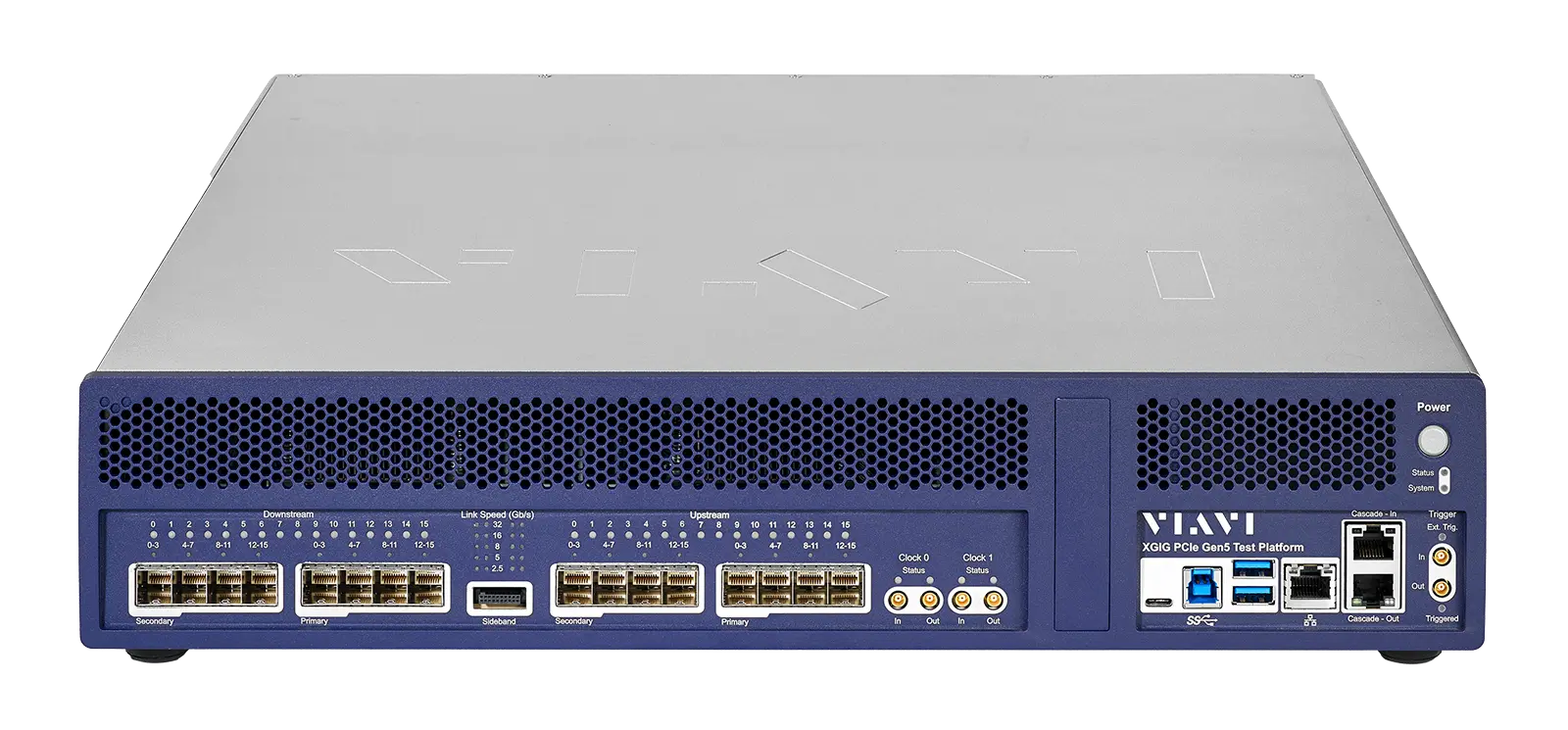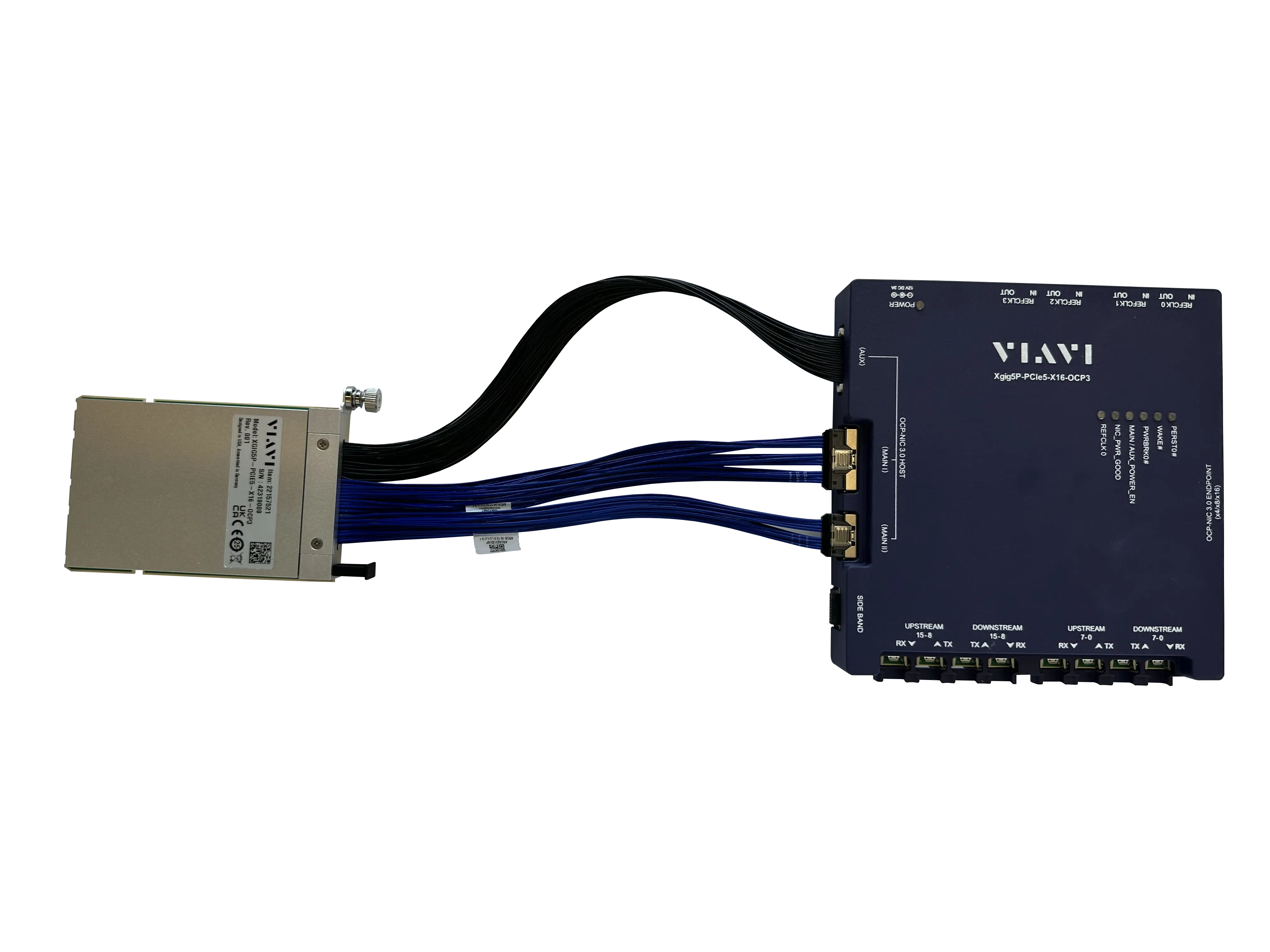
Xgig 16-lane OCP3 Interposer Xgig5P-PCIe5-X16-OCP3 for PCI Express 5.0
16-lane OCP NIC 3.0 interposer that taps host-system PCIe 5.0 signals at up to 32 GT/s for input to the VIAVI Xgig Analyzer.
- Maximum data rate
- 32 GT/s (PCIe 5.0)
- Downward compatible data rates
- 2.5, 5.0, 8.0G and 16GT/s
- Link configurations
- 1 link of 16 lanes, 2 links of 8 lanes or 4 links of 4 lanes
- DUT form factor
- OCP NIC 3.0
Overview
The VIAVI Xgig 16-lane OCP3 Interposer for PCI Express 5.0 (Xgig5P-PCIe5-X16-OCP3) is designed for developing, debugging and performance tuning OCP NIC 3.0 devices used in data centers. The OCP NIC 3.0 specification was created by the Open Compute Project to define a data center optimized form factor for PCIe devices.
The interposer provides the connection between the VIAVI PCIe 5.0 Analyzer/Exerciser/Jammer platform and an OCP system under test. Bidirectional PCIe 5.0 protocol data on up to 16 lanes can be captured at 32 GT/s, and the interposer supports 1 link of 16 lanes, 2 links of 8 lanes or 4 links of 4 lanes with the appropriate licenses.
High-speed linear signal redrivers buffer the system data signals across the interposer between the host system and the OCP NIC 3.0 device under test, so that a clean signal reaches the Analyzer for protocol capture and analysis with little or no tuning. Interposer power comes from a supplied power brick and is independent of the host system.
Setup and operating modes
An OCP 3.0 NIC is inserted into the interposer base pod, and the front-end module is inserted into the OCP NIC 3.0 bay of a data center server. Cables connect the interposer to the VIAVI PCIe 5.0 Analyzer/Exerciser/Jammer platform, and Xgig analysis tools run on a local or remote Windows PC. In Analyzer mode, DUT data is tapped from both upstream and downstream paths; in Analyzer/Jammer mode, data flows through the Analyzer and is modified between devices; in Analyzer/Exerciser mode, data is sourced from the Analyzer chassis and sent to the server device under test through the interposer.
Typical uses include debug and verification of new OCP NIC 3.0 PCIe controller ICs, new server designs, FPGA firmware, validation of system BIOS and software, and manufacturing test.
Key Features
- Operates up to 32 GT/s, PCIe 5.0 data rates
- Downward compatible with PCIe 1.0, 2.0, 3.0 and 4.0 and data rates of 2.5, 5.0, 8.0 and 16 GT/s
- Supports 1 link of 16 lanes, 2 links of 8 lanes or 4 links of 4 lanes with proper licenses
- OCP NIC 3.0 DUT plugs directly into the interposer
- Data path uses high-speed linear redrivers for good signal capture with little or no tuning
- Supplied with high-quality custom cables for Analyzer attachment
- Four coax cables provided for optional clocking sources
- Supports Analyzer side-band signal triggering and capture via custom cable
- Supports Jammer error injection for deep system analysis and debug
- Interposer power independent of host system via included 12V/3A power brick
- LEDs indicate power and operating status
- Provides consistent, repeatable capture of link training, equalization negotiation and other data
- Supported by the Xgig tool suite including Trace Control, Expert and Serialytics
Specifications
| Maximum data rate | 32 GT/s (PCIe 5.0) |
|---|---|
| Downward compatible data rates |
2.5, 5.0, 8.0G and 16GT/s
PCIe 1.0, 2.0, 3.0 and 4.0
|
| Link configurations |
1 link of 16 lanes, 2 links of 8 lanes or 4 links of 4 lanes
With proper licenses
|
| DUT form factor | OCP NIC 3.0 |
| Analyzer data cables |
8
Custom high-performance cables
|
| Reference clock cables |
4
Coax cable for optional clock
|
| Size (Base Pod) | 175 x 167 x 35 mm |
|---|
| Power brick |
120/220 input, 12V/3A output
Interposer power independent of host system
|
|---|
Specifications are taken from the manufacturer's documentation. See the datasheet for complete and current values.
Applications
- OCP NIC 3.0 device development and debug
- Verification of new PCIe controller ICs
- New server and system hardware design verification
- FPGA firmware tuning
- System BIOS and software validation
- Manufacturing test
- PCIe trace capture with filtering and triggering
- Error injection for deep system analysis
Included
- Xgig5P-PCIe5-X16-OCP3 16-lane Interposer Base Pod (1)
- OCP NIC 3.0 Front-end module (1)
- Custom high-performance cables (8)
- Sideband cable to analyzer (1)
- Coax cable for optional clock (4)
- Power brick, 120/220 input, 12V/3A output (1)
- Bracket kit (1)
- Quick Start Guide (1)
Options & Accessories
| Option | Description |
|---|---|
| Xgig-Intpsr-C-Hx | x-year extended hardware warranty — x=1, 2, 3, 4 |