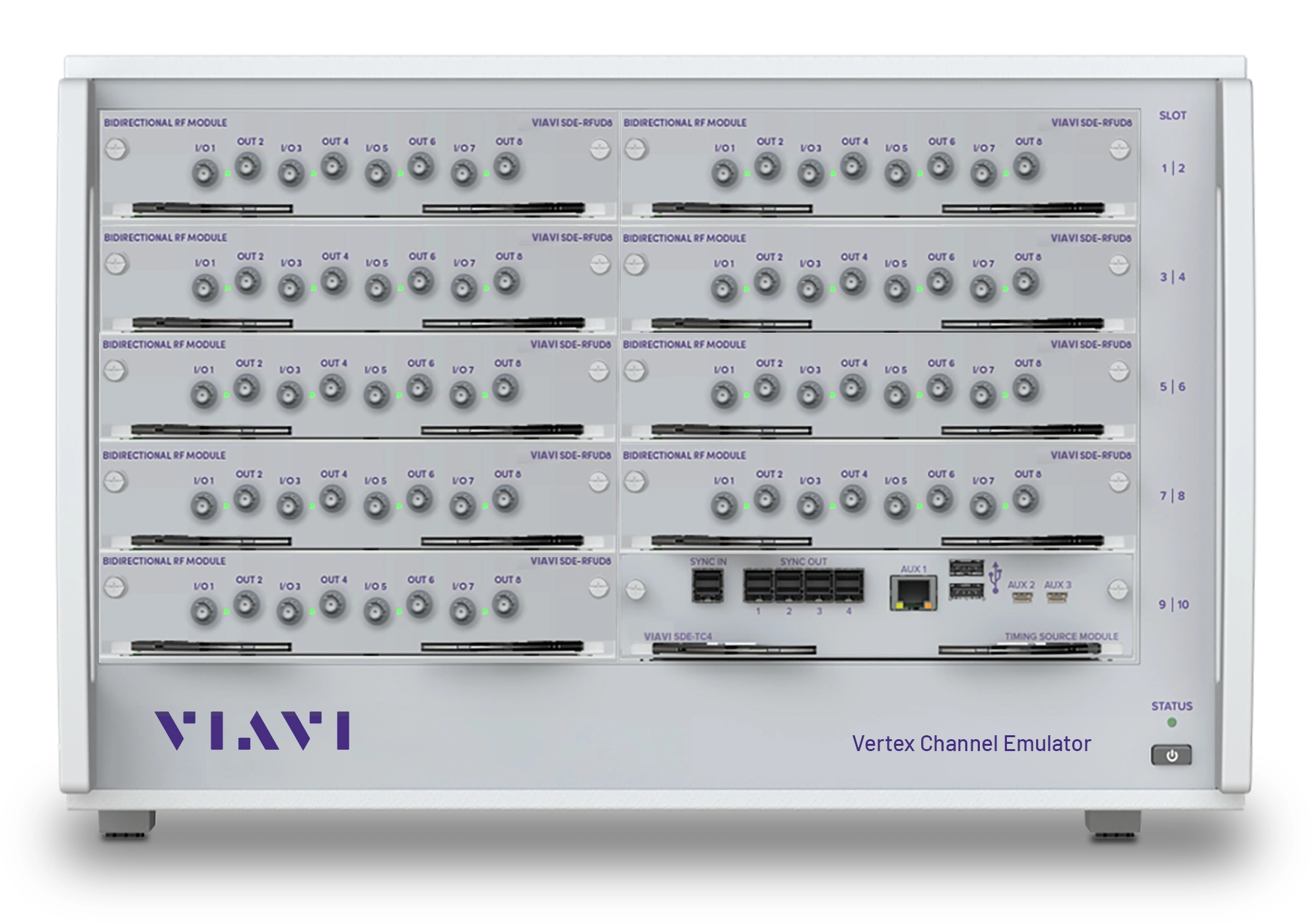
VIAVI Vertex Channel Emulator for Cellular, Wi-Fi, Satellite and Defense RF Channel Emulation
Modular RF channel emulator from 100 MHz to 7.325 GHz, extensible to FR3 with the optional FR3 MIMO Converter, for 5G/6G and Wi-Fi 7/8 test.
- RF configuration, single instrument
- 4x4 Bidirectional; 16x16 Unidirectional; Up to 8x8 Bidirectional
- RF configuration, multi-instrument
- Up to 64x8 Bidirectional (TDD and FDD)
- RF inputs
- Up to 32 (single instrument); Up to 128 (multi-instrument)
- RF outputs
- Up to 32 (single instrument); Up to 128 (multi-instrument)
Overview
The VIAVI Vertex Channel Emulator is an RF channel emulation platform that replicates the noise and spatial conditions of wireless channels in the lab, so performance issues can be isolated early in development. It covers cellular, Wi-Fi, satellite and defense applications, from SISO or 2x2 MIMO up to high-channel-density scenarios such as MIMO beamforming, MIMO OTA, carrier aggregation and massive MIMO.
The platform combines a modular RF front end with a signal-processing core. Separate RF modules are optimized for unidirectional or bidirectional use and different frequency bands, and each RF module has its own local oscillator, allowing multiple carrier frequencies in one instrument. RF and DSP modules are field-replaceable. A single 6U instrument supports up to 72 ports and 256 digital links, and up to four Vertex units can be combined into one system with the Vertex Baseband Synchronizer (VBS).
Vertex 6.0
Vertex 6.0 adds a new RF module with 4 RF chains (4 input/output ports and 4 output ports), 400 MHz bandwidth and native phase coherence, extending FR1 coverage to 7.125 GHz; the previous module stopped at 5.925 GHz. It supports 4096 QAM at 320 MHz for Wi-Fi 7/8 in modular configurations from 2x2 to 8x8. The FR3 MIMO Converter, a 2U up/down converter with 1 GHz instantaneous bandwidth and four 4x4 channels per module, extends coverage into the FR3 cmWave range. All upgrades install into an existing Vertex chassis in the field.
Channel modeling and control
A built-in propagation library provides standard channel models (including 5G TDL and CDL) and supports editing of standard and user-defined models, classical and 2D/3D geometrical models, and up to 16 independent nodes for mesh networks. Optional VIAVI Raytracing adds site-specific scenarios including moving-object modeling for ISAC. The graphical user interface shares its features with the VR5 HD channel emulator, and remote programming over TCP/IP (telnet or SSH) is backward compatible with the VR5 HD. Live Streaming Dynamic Environment Emulation (LSDEE) allows channel parameters to be changed in real time without predefined states.
Virtual drive testing
Vertex supports up to sixteen SISO cells or eight 2x2 MIMO cells on one instrument. With the Live2Lab Virtual Drive Test-Conversion Tool, field log files (for example QXDM or Accuver) are converted into repeatable drive-route simulations in the lab.
Key Features
- Scalable from two bidirectional RF channels up to 72 unidirectional RF ports in one instrument
- Up to 72 ports and 256 digital links in 6U rack height
- Field-replaceable RF and DSP modules
- Independent local oscillator per RF module for multiple carrier frequencies
- Vertex 6.0 RF module with 4 RF chains, 4 input/output ports and 4 output ports
- 400 MHz native bandwidth with native phase coherence for MU Massive MIMO
- Full 5G NR FR1 coverage to 7.125 GHz on a single instrument
- 4096 QAM at 320 MHz for Wi-Fi 7/8, modular from 2x2 to 8x8
- Optional FR3 MIMO Converter with 1 GHz instantaneous bandwidth for cmWave testing
- Up to 4 Vertex instruments synchronized with the Vertex Baseband Synchronizer (VBS)
- Up to 16x16 independent channel models for 16-node mesh networks
- Built-in propagation library with standard and user-defined channel models
- Optional VIAVI Raytracing for site-specific scenarios and ISAC moving-object modeling
- Live Streaming Dynamic Environment Emulation (LSDEE)
- Remote programming via TCP/IP with telnet or SSH, backward compatible with VR5 HD
- GUI with connection setup library, cable connection diagram and real-time per-port power tracking
- Real-time and IQ playback fading
Specifications
| RF configuration, single instrument | 4x4 Bidirectional; 16x16 Unidirectional; Up to 8x8 Bidirectional |
|---|---|
| RF configuration, multi-instrument | Up to 64x8 Bidirectional (TDD and FDD) |
| RF inputs | Up to 32 (single instrument); Up to 128 (multi-instrument) |
| RF outputs | Up to 32 (single instrument); Up to 128 (multi-instrument) |
| Digital channels |
Up to 256 (single instrument); Up to 1024 (multi-instrument)
Digital channel density = 16x16 (single instrument)
|
| Ports and digital links | Up to 72 ports and 256 digital links in one 6U rack height |
| Multi-instrument system | Up to 4 Vertex instruments with the Vertex Baseband Synchronizer (VBS) |
| Frequency range |
100 MHz to 7.325 GHz
Extensible to 23.5 GHz with the optional FR3 MIMO Converter. The web page states FR1 coverage up to 7.125 GHz.
|
|---|---|
| Bandwidth |
40 MHz, 100 MHz, 200 MHz, 400 MHz, 600 MHz*, 800 MHz*, 1000 MHz*, 1200 MHz*
*By stitching multiple channels; later SW versions
|
| Input level range | -50 to +15 dBm |
|---|---|
| Input level resolution | 0.1 dB |
| Input damage level | +33 dBm (Peak) |
| RF output level min/max range | -110 to -10 dBm (RMS) |
| RF output level resolution | 0.1 dB |
| Input and output power meter modes | Continuous; RF burst-triggering for gated input signals |
| Residual EVM (5G NR 100 MHz), 100 MHz to 1.5 GHz |
<-43 dB
typical
|
| Residual EVM (5G NR 100 MHz), 1.5 GHz to 5 GHz |
<-40 dB
typical
|
| Residual EVM (5G NR 100 MHz), 5 GHz to 7.325 GHz |
< -37 dB
typical; <-43 dB with optional FR3 MIMO Converter
|
| Residual noise |
Better than -165 dBm/Hz
at a set output level of -45 dBm
|
| RF port VSWR | 1.5:1 |
| Independent paths | Up to 24 paths per digital channel |
|---|---|
| Delay | 0 to 1 s at bandwidths >=100 MHz; 0 to 2 s at bandwidths =40 MHz; 0.1 ns resolution |
| Relative path loss | 0 to 40 dB |
| Dynamic channel parameters | Sliding delay (moving propagation); Birth-death delay; 3GPP High-Speed Train (HST) profiles log normal (shadow fading) |
| Insertion delay |
Minimum 2.65 μs
value increases with topology and number of Vertex units
|
| DEE and LSDEE controllable parameters | State duration, channel output level, AWGN on/off, C/N, path on/off, relative power and delay, LOS AoA, K factor, frequency shift, Doppler velocity, MIMO branch phase, power imbalance, and correlation, link phase and loss, bulk delay, path phase, geometrical characters, port Doppler |
| Channel model update rate |
100 times per second
DEE / LSDEE
|
| DEE start and play methods | Start: Triggered, free play; Play: Run for N loops, wrap around; Smoothing supported |
| Standards-based models | LTE, Wi-Fi (802.11a/b/g, 802.11n, 802.11 ac, 802.11 ax), IMT-A, WiMAX, UMTS, CDMA2000, HSPA, GSM, SCM/SCME (ITU-R M.2135), WINNER, Butler, 5G TDL and CDL, D2D |
| Custom models |
Create custom channel models or edit any of the standard channel models in the library
Optional VIAVI Raytracing software for site-specific scenarios including ISAC moving-object modeling
|
| Fading mode | Classical, GCM, 3D GCM, MIMO OTA |
| IQ-playback fading | Supports IQ playback fading |
| Fading types | Rayleigh, Rician, pure Doppler, frequency shift, phase shift, Log normal (Shadow) fading |
|---|---|
| Fading Doppler | Up to 12 kHz |
| Doppler frequency shift | -2 MHz to 2 MHz |
| Relative phase | 0-360°, 0.1° resolution |
| Rician K factor | -30 to +30 dB |
| Level crossing rate (LCR) accuracy | < ±2.5% deviation from theoretical LCR curve of the simulated vehicle velocity |
| Fading power spectrum | classical 6dB, flat, classical 3 dB, rounded, rounded 12 dB, bell |
| Correlation | programmable complex correlation between paths |
| C/N ratio | -40 to +40 dB |
|---|---|
| Accuracy | ±0.1 dB |
| Bandwidth | up to 400 MHz |
| Settable modes | C/N, Eb/No, N |
| Non-contiguous carrier aggregation | Up to 16 independent carriers (single instrument); Up to 64 independent carriers (multi-instrument) |
|---|---|
| Mesh capacity, single instrument | Up to 16 nodes with up to 2 sec independent delay |
| Virtual drive test cells | Up to sixteen SISO cells or eight 2x2 MIMO cells on one instrument |
| MIMO OTA anechoic chamber |
Up to 32 RF probes and two carriers with 16 dual polarized probes or 8 dual polarized probes on one instrument
Reverberation chambers: up to four carriers aggregated on one instrument
|
| Control interface |
PC-based graphical user interface; Remote programming through ethernet
TCP/IP with telnet or SSH
|
| 10 MHz internal reference accuracy | 1 ppm |
|
Frequency range
TK1197
|
4.9 GHz to 20 GHz (useable 20-23.6 GHz)
Reduced specification above 20 GHz; the web page quotes 5 to 23.6 GHz
|
|---|---|
|
Instantaneous bandwidth
TK1197
|
1 GHz |
|
Number of TX/RX channels
TK1197
|
4 per module (max 4 MIMO Modules) |
|
Carriers/bandwidth
TK1197
|
4CC x 100 MHz |
|
IF frequency range
TK1197
|
1.0 GHz to 2.7 GHz
band specific
|
|
Duplexing mode
TK1197
|
TDD/FDD |
|
Up converter residual EVM
TK1197
|
Typ: 0.5% or 46dB @ -10 dBm 1CC 100 MHz
Max: 3.2 % or 30 dB @ -25 dBm per CC 100 MHz 4CC
|
|
Down converter average noise figure
TK1197
|
Typ: 10 dB; Max: 14 dB
With RX RF attenuator set to 0dB; default attenuator 6 dB increases noise figure by 6 dB
|
|
Height (2U)
TK1197
|
8.825 cm (3.47”) without feet; 9.825 cm (3.87”) including feet |
|
Weight
TK1197
|
5kg (4x4), 8kg (16x16) |
|
Power dissipation
TK1197
|
4 x 4 configuration (1 MIMO Module): <50 W DC, <55 W AC; 16 x 16 configuration (4 MIMO Modules): <160 W DC, <175 W AC |
|
5G NR FR2 bands
Vertex MB-HFC
|
N257 N258 N259 N260 N261 N262
Must be used with Vertex Channel Emulator
|
|---|---|
|
Frequency coverage
Vertex MB-HFC
|
24.25 GHz to 48.2 GHz |
|
Channels
Vertex MB-HFC
|
4 Independent channels |
Specifications are taken from the manufacturer's documentation. See the datasheet for complete and current values.
Applications
- MIMO beamforming
- MIMO OTA in anechoic and reverberation chambers
- Carrier aggregation
- Massive MIMO and antenna array systems
- MU Massive MIMO at 64x8
- 5G NR FR1 conformance to 7.125 GHz
- 6G FR3 cellular validation
- Wi-Fi 7/8 chipset, access point and device test
- Wi-Fi 6/6e, Wi-Fi 5 and Wi-Fi 4 including MLO
- Device conformance and performance verification
- Virtual drive testing
- Mesh networks
- Military mesh and drone communications
- Integrated sensing and communications (ISAC)
- Satellite (NTN) and aeronautical applications
- RAN vendor acceptance benchmarking
- Indoor and dense-urban coverage validation
- Multi-vendor RAN integration labs
Options & Accessories
| Option | Description |
|---|---|
| TK1197 | FR3 MIMO Converter — Supplied with 1 MIMO Module as standard |
| HW1000 | Adds 2nd MIMO Module — For the FR3 MIMO Converter |
| HW1001 | Adds additional 2 RF Modules — For the FR3 MIMO Converter |
| Vertex MB-HFC | Vertex Multi-Band High Frequency Converter — Extends Vertex to 5G NR FR2 bands N257, N258, N259, N260, N261 and N262 |
| VBS | Vertex Baseband Synchronizer — Integrates up to 4 Vertex instruments into one system |
| Live2Lab VDT-CT | Live2Lab Virtual Drive Test-Conversion Tool — Converts drive test log files into reproducible lab drive route simulations |
| VIAVI Raytracing | VIAVI Raytracing software — Site-specific scenario emulation including moving object modeling for ISAC |
Documents & Resources
Related Products
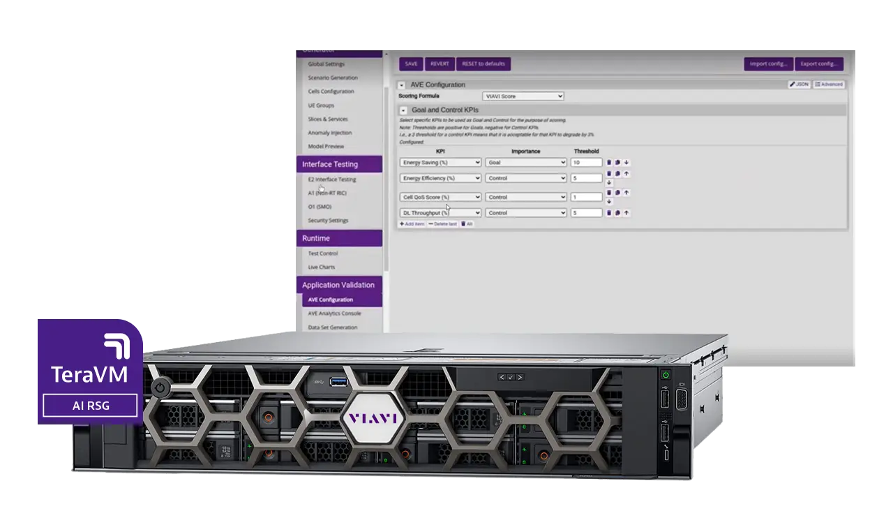
Software-based RAN digital twin that simulates, develops and validates 4G, 5G, 6G and NTN network behavior and xApps/rApps without physical infrastructure.
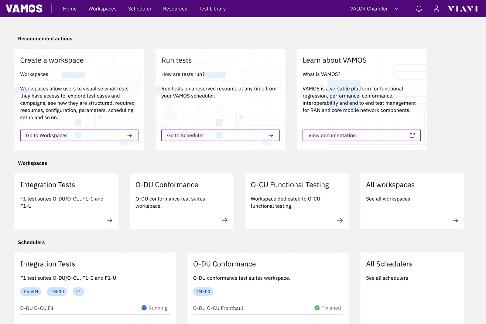
Cloud-based platform that automates wireless test campaigns, cases and executions across VIAVI and third-party lab tools.
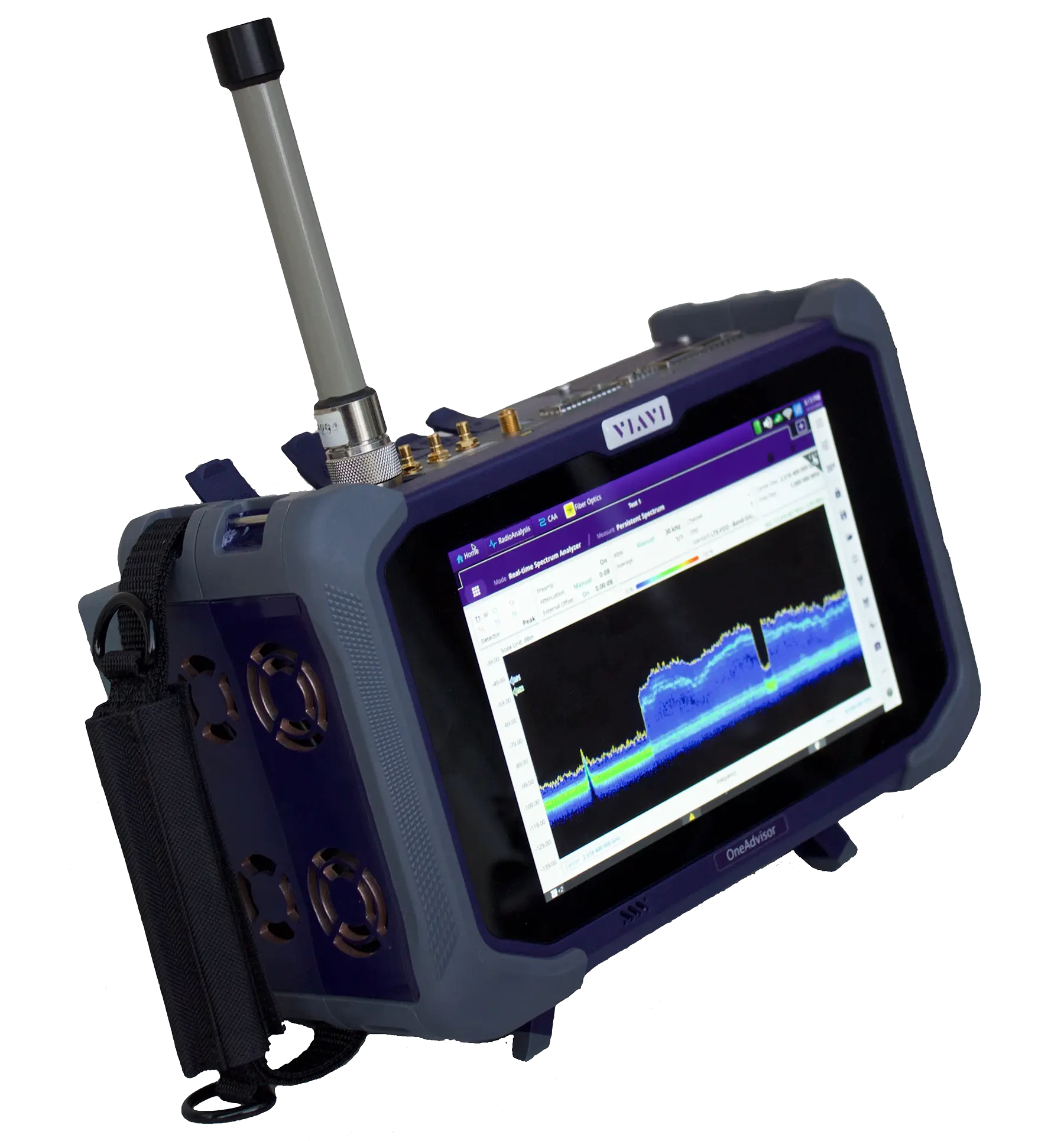
Modular field test platform combining RF spectrum and signal analysis, cable and antenna, fiber and Ethernet transport testing in one portable unit.
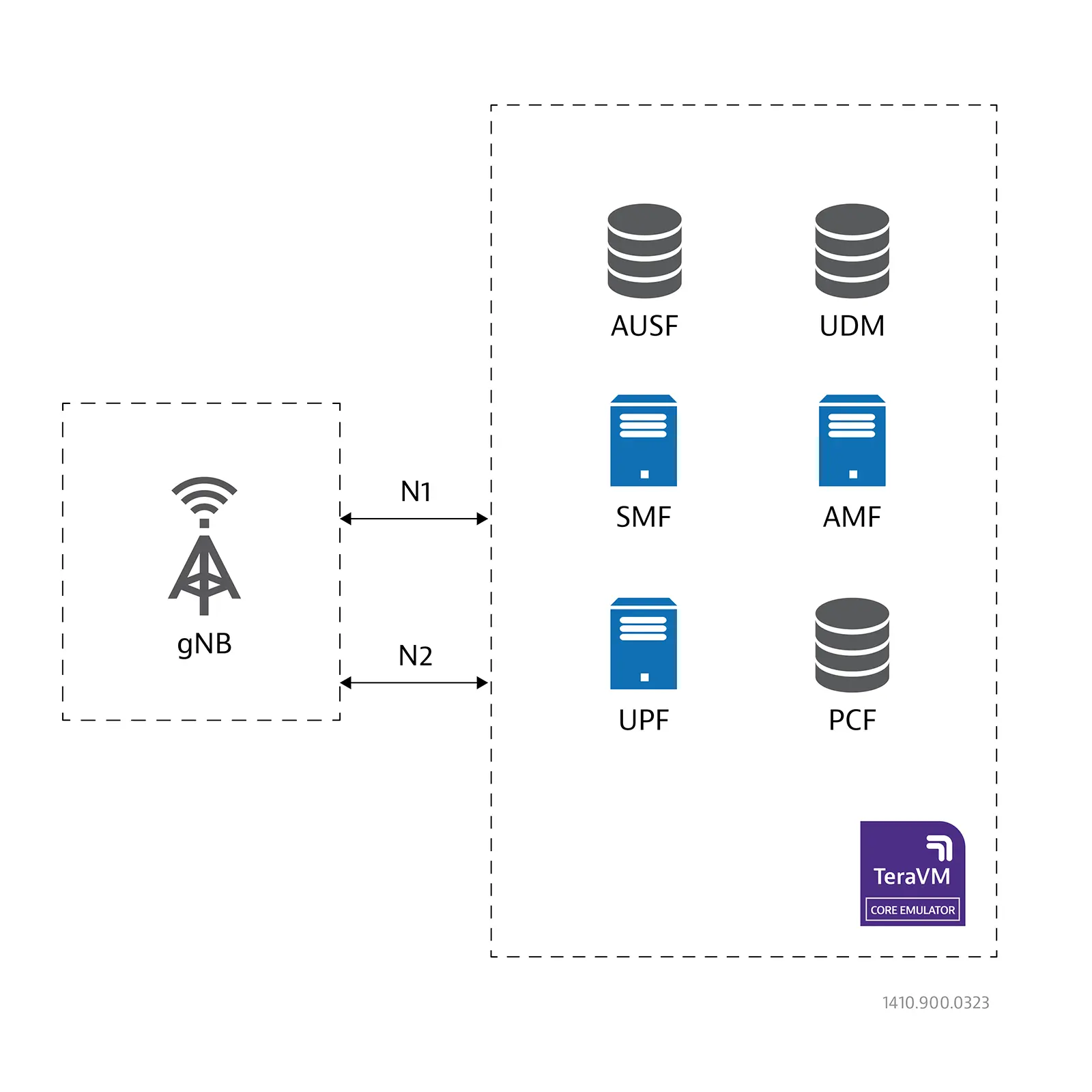
Virtualized 5G core network emulator that works with the TM500 test mobile for wrap-around testing of 5G gNBs in SA and NSA modes.
Network tester that emulates thousands of mobile devices to test 4G, 5G and Open RAN base stations across the full protocol stack.
O-RAN fronthaul extension of the TM500-C 5G Test Mobile that tests O-DUs directly over eCPRI, without an O-RU, across multiple O-RAN profiles.
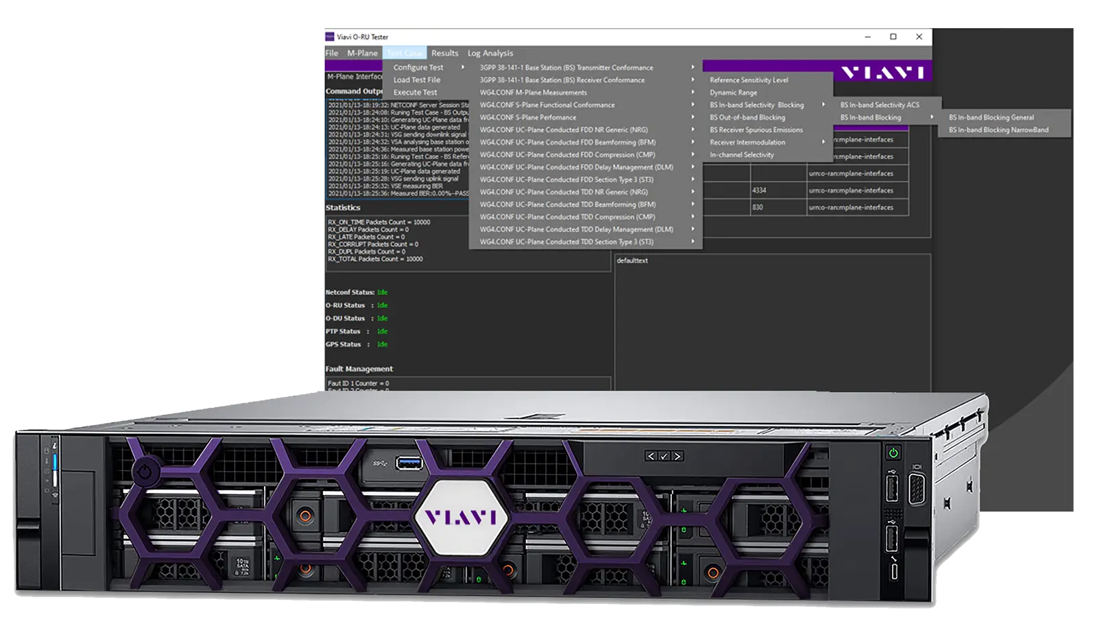
Test system that validates O-RAN Radio Units for conformance, interoperability and performance using an emulated O-DU and Rohde & Schwarz RF instruments.