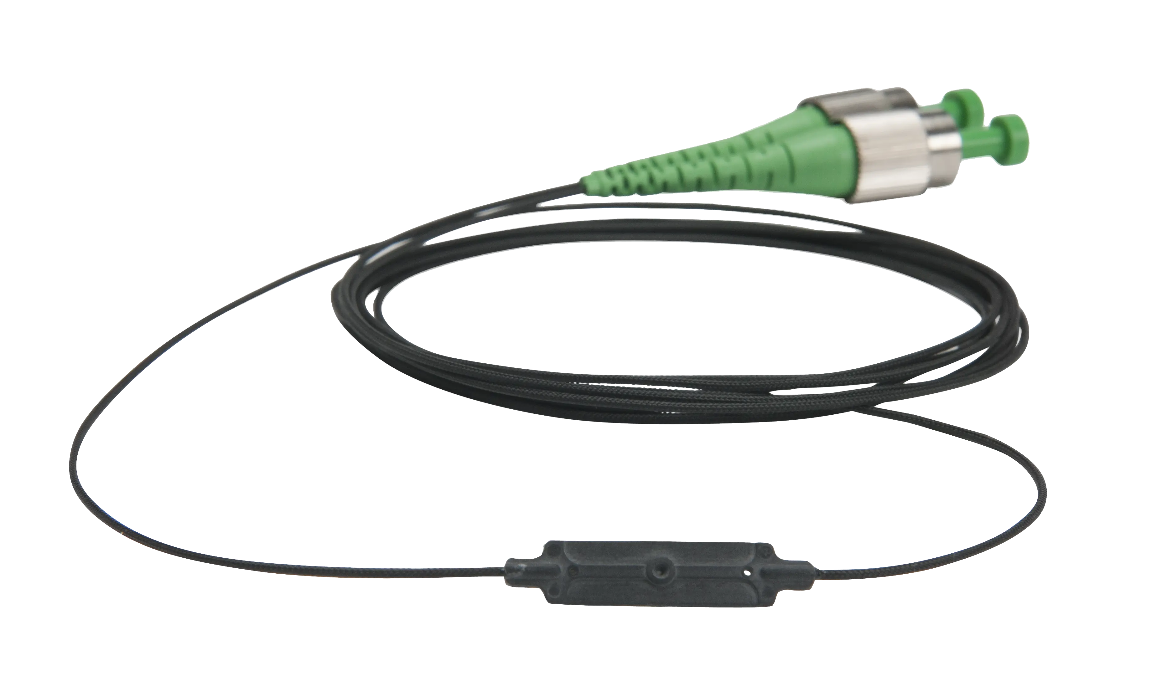
os3200 Non-Metallic Optical Strain Gage (FBG, Epoxy-Mounted)
Small, non-metallic, epoxy-mounted optical strain gage based on fiber Bragg grating (FBG) technology with ± 5,000 με strain limits.
- Strain sensitivity
- ~ 1.2 pm/με
- Gage length
- 10 mm
- Operating temperature range
- -40 to 60 °C (80 °C max)
- Strain limits
- ± 5,000 με
Overview
The os3200 is a small, non-metallic, epoxy-mounted optical strain gage based on fiber Bragg grating (FBG) technology. A self-adhesive backing holds the sensor body in place and protects the FBG while epoxy is injected; the epoxy encapsulates the FBG and bonds it to the surface of the structure. Installation takes a few minutes, and measurements can be taken once the epoxy has cured for 24 hours at room temperature.
In side-by-side comparisons with foil strain gages, the os3200 is equally sensitive and accurate, while offering a greater strain range and 100 times more fatigue life. The gage is qualified for use in mild environments.
The sensor can be used alone or in series as part of an FBG sensor array, with a double-ended design that allows many sensors to be multiplexed on one fiber. Multiple gages can be arranged in close proximity at 0, 45 and 90 degrees for strain rosette measurements.
Each sensor ships with a Sensor Information Sheet listing the gage factor and calibration coefficients needed to convert wavelength information into engineering units. The ENLIGHT Sensing Software includes the os3200 in its sensor templates and provides a utility to calculate, record, display and transmit data for large sensor networks.
Key Features
- Fast, simple, repeatable installation
- Double-ended design supports multiplexing of many sensors on one fiber
- Qualified to same rigorous standards used for comparable electronic gages
- Gage installation and protection achieved with same methods as conventional electronic gages
- Patented micro opto-mechanical technology
- Included in ENLIGHT's sensor templates for quick and easy optical to mechanical conversions
- Sensor Information Sheet with gage factor and calibration coefficients provided with each sensor
- Can be arranged at 0, 45 and 90 degrees for strain rosette measurements
Specifications
| Strain sensitivity |
~ 1.2 pm/με
Actual gage factor provided with gage
|
|---|---|
| Gage length | 10 mm |
| Operating temperature range |
-40 to 60 °C (80 °C max)
Prolonged exposure to maximum temperature could reduce performance. The newer Luna data sheet lists -40 to 60° C without the 80 °C max
|
| Strain limits | ± 5,000 με |
| Maximum drift |
50 με
40 temperature cycles -40 to 60° C
|
| Dimensions |
See Diagram Below
Dimensional drawing in data sheet
|
|---|---|
| Weight | 1.0 g |
| Carrier material | Santoprene™ |
| Cable length | 1 m (± 10 cm), each end |
| Fiber type | SMF28-Compatible |
| Cable type | 1 mm Fiberglass Braid |
| Connectors | FC/APC optional |
| Cable bend radius | ≥ 17 mm |
| Fastening methods |
Epoxy
See installation guide for details
|
| Peak reflectivity (Rmax) | > 70% |
|---|---|
| FWHM (-3 dB point) | 0.25 nm (± .05 nm) |
| Isolation |
> 15 dB
@ ± 0.4 nm around center wavelength
|
| Part number format |
os3200-wwww-1xx-1yy
wwww = wavelength; 1xx = cable 1 length & connector; 1yy = cable 2 length & connector
|
|---|---|
| Wavelength (wwww) |
Standard - 1460 to 1620 nm in 4 nm intervals
+/- 1nm
|
| Cable length (1xx / 1yy) | 1 m Standard, Cable Length |
Specifications are taken from the manufacturer's documentation. See the datasheet for complete and current values.
Applications
- SHM for civil and geotechnical structures
- SHM for energy systems
- Structural test and model validation
- Structures (bridges, dams, tunnels, mines, buildings, oil platforms)
- Energy (wind turbines, oil wells, pipelines, nuclear reactors, generators)
- Transportation (railways, trains, roadways, specialty vehicles, cranes)
- Marine vessels (hull, deck, cargo containers)
- Aerospace (airframes, composite structures, wind tunnels, static and dynamic tests)
- Homeland security (perimeter intrusion, heat detection, security gate monitoring)
Included
- Sensor Information Sheet (gage factor and calibration coefficients)
Options & Accessories
| Option | Description |
|---|---|
| UT | Unterminated — Termination type for cable 1 (xx) or cable 2 (yy) |
| FC | FC/APC Connector — Termination type for cable 1 (xx) or cable 2 (yy) |
Documents & Resources
Related Products
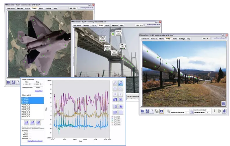
Data acquisition, computation, storage and analysis software for fiber optic sensor networks based on Luna HYPERION interrogators.
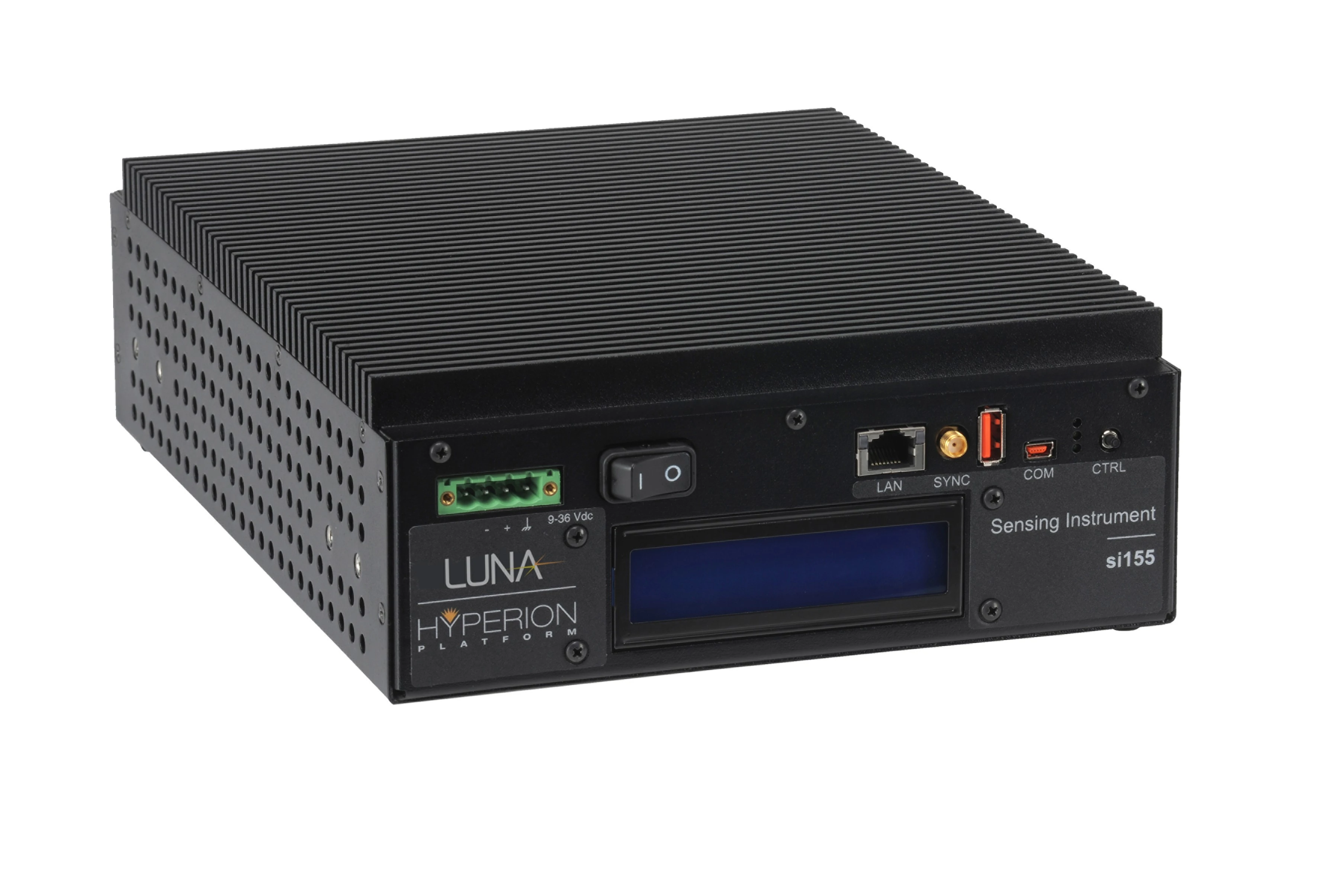
Industrial-grade fan-less optical sensing interrogator with static and dynamic full-spectrum analysis on up to 4 parallel 160 nm wide channels.
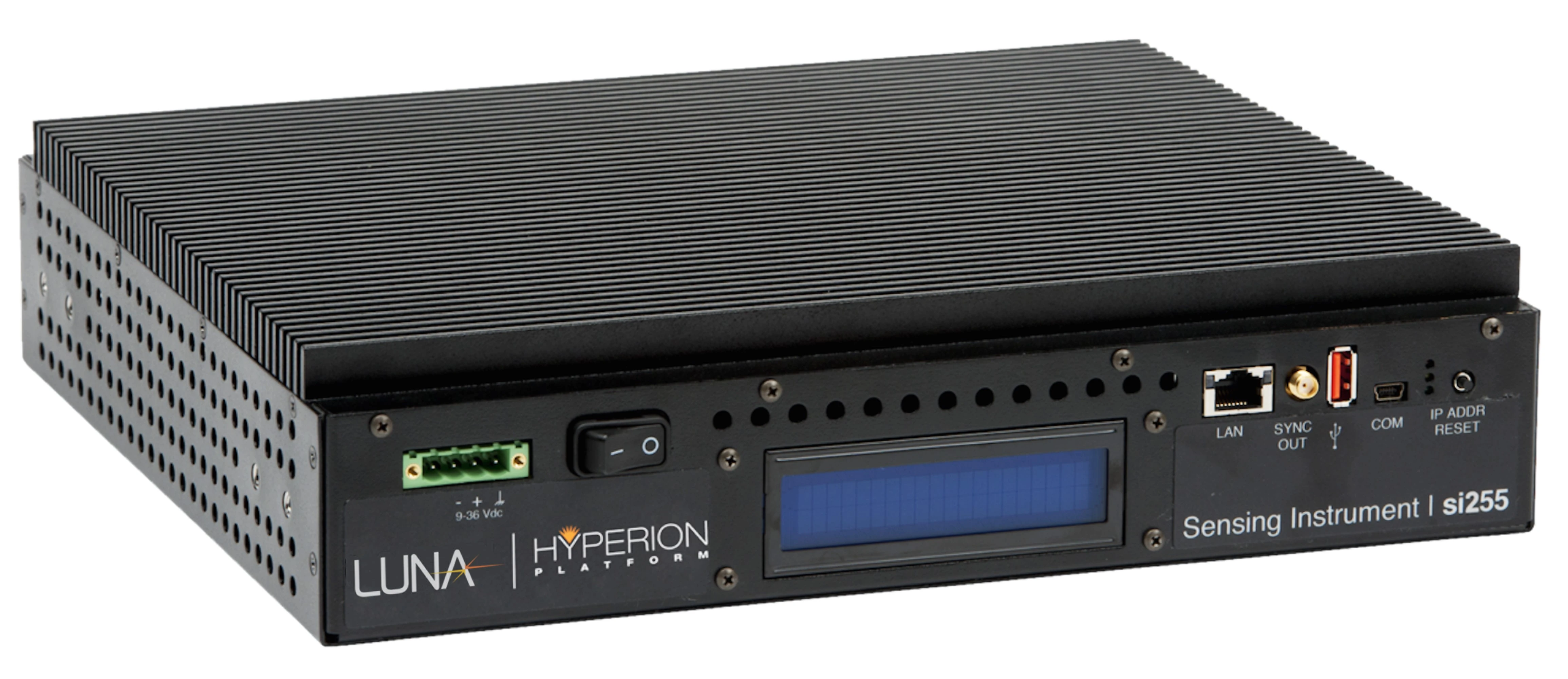
Industrial-grade fan-less interrogator measuring nearly 1000 FBG, LPG, FP and MZ sensors on 16 parallel, 160 nm wide channels.
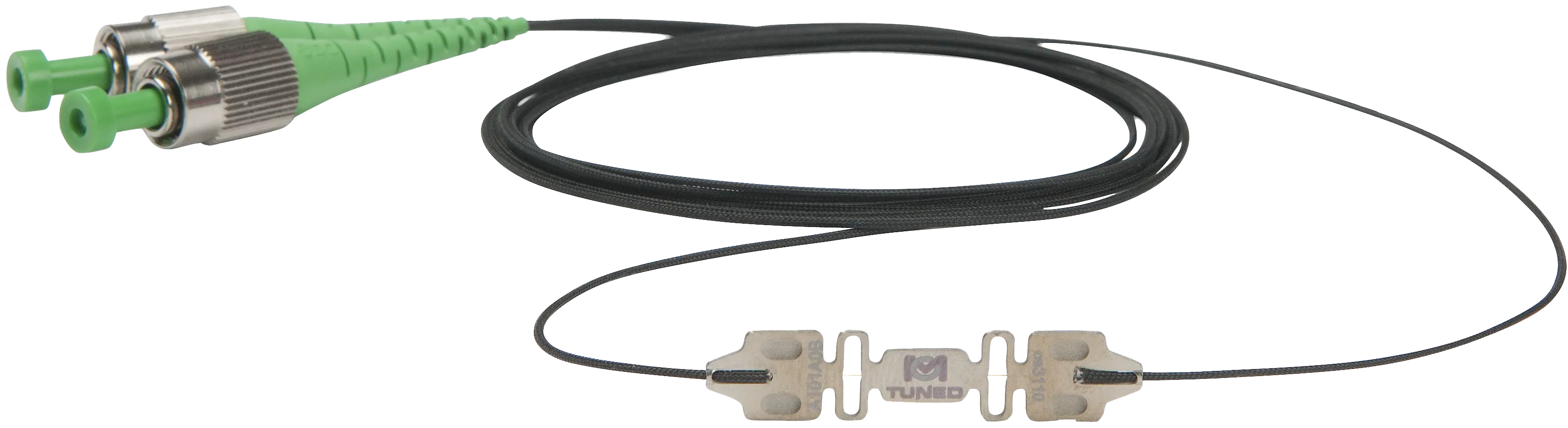
Fiber Bragg grating optical strain gage with a stainless steel carrier for spot-weld or epoxy mounting on structural surfaces.