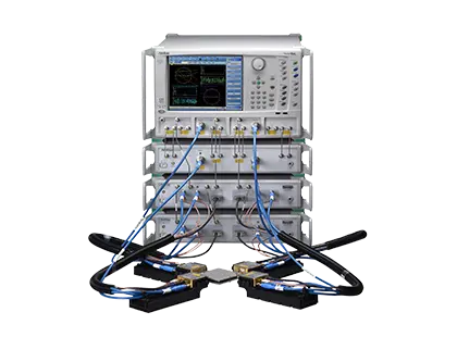
VectorStar ME7838G4 4-Port Broadband Vector Network Analyzer, 70 kHz to 220 GHz
4-port broadband VNA system with single-sweep coverage from 70 kHz to 220 GHz and waveguide-band extension to 1.1 THz.
- Broadband frequency range
- 70 kHz to 220 GHz
- Operational frequency range
- 40 kHz to 226 GHz
- Waveguide band configuration
- 50 GHz to 1.1 THz
- Number of test ports
- 4
Overview
The Anritsu VectorStar ME7838G4 is a 4-port broadband vector network analyzer system that provides a continuous single sweep from 70 kHz to 220 GHz, without concatenating multiple systems. It is operational from 40 kHz to 226 GHz through a single coaxial-mode connector.
The system uses the Anritsu MA25400A mmWave module. This module combines Anritsu-developed Nonlinear Transmission Line (NLTL) technology in a compact package with a 0.6 mm test port connector. Each module weighs 0.27 kg (0.6 lbs), so it can be positioned easily on a wafer probe station. Port power is levelled in real time inside the module above 54 GHz, without the need for calibration software correction tables.
The broadband configuration is built around an MS4647B VectorStar VNA together with the 3739C and 3736B broadband test sets, an MN4697C four-port test set and four MA25400A mmWave modules. Covering near-DC through G band lets W-band devices be characterized well through the second harmonic of their operating frequency, which supports more accurate device modeling.
Waveguide configuration
The ME7838G4 can also be configured for waveguide-band operation from 50 GHz to 1.1 THz. This is done with WR5 adapters on the MA25400A modules, Anritsu 3744A-EE/EW modules, or external VDI frequency extension modules. The waveguide setup can extend the broadband system or run as a waveguide-only system.
Upgrade path
Existing ME7838A4X 125 GHz and ME7838D4 145 GHz broadband systems can be upgraded to 220 GHz by adding the MA25400A mmWave module.
Key Features
- Single-sweep 4-port coverage from 70 kHz to 220 GHz, operational from 40 kHz to 226 GHz
- Waveguide-band coverage from 50 GHz to 1.1 THz
- MA25400A NLTL mmWave modules with 0.6 mm test port connector
- Calibration and measurement stability of 0.1 dB over 24 hrs
- Measurement speed of 310 ms for 401 points at 10 kHz IFBW
- Real-time power leveling without calibration software correction tables
- Supports tri-axial Kelvin bias tee connections for on-wafer device biasing up to 220 (226) GHz
- Compact mmWave modules, 0.6 lb and 1/50 the volume of traditional mmWave modules
- Upgrade path from ME7838A4X and ME7838D4 systems to 220 GHz
- Spectrum analyzer option (Option 49) available on the broadband configuration
- Noise figure measurements from 30 GHz to 125 GHz with Option 41 and 3744A-Rx receiver module
- Differential noise figure measurements with Option 48
Specifications
| Broadband frequency range |
70 kHz to 220 GHz
Single sweep
|
|---|---|
| Operational frequency range | 40 kHz to 226 GHz |
| Waveguide band configuration |
50 GHz to 1.1 THz
In waveguide bands
|
| Number of test ports | 4 |
| Test port connector |
0.6 mm
MA25400A mmWave module
|
| Frequency resolution | 1 Hz |
| Dynamic range | 112 dB at 67 GHz, 108 dB at 110 GHz, 100 dB at 140 GHz, and 102 dB at 220 GHz |
|---|---|
| Measurement speed | 310 ms for 401 points at 10 kHz IFBW |
| Calibration and measurement stability | 0.1 dB over 24 hrs |
|
> 0.01 to < 2.5 GHz
Option 51
|
111 dB
Typical, 10 Hz IFBW, port 1 or 3 driving
|
|---|---|
|
> 54 to 60 GHz
Option 51
|
112 dB
Typical, 10 Hz IFBW
|
|
> 105 to 110 GHz
Option 51
|
106 dB
Typical, 10 Hz IFBW
|
|
> 140 to 150 GHz
Option 51
|
100 dB
Typical, 10 Hz IFBW
|
|
> 200 to 220 GHz
Option 51
|
98 dB
Typical, 10 Hz IFBW
|
|
> 220 to 226 GHz
Option 51
|
85 dB
Typical, 10 Hz IFBW
|
|
> 54 to 60 GHz
Option 51, Option 62
|
–116 dBm
Typical
|
|---|---|
|
> 200 to 220 GHz
Option 51, Option 62
|
–113 dBm
Typical
|
|
> 0.01 to < 2.5 GHz
Option 51
|
8 dBm
Typical, ports 1 and 3
|
|---|---|
| > 60 to 67 GHz |
–3 dBm
Typical
|
| > 200 to 220 GHz |
–15 dBm
Typical
|
| > 220 to 226 GHz |
–18 dBm
Typical
|
| Power resolution |
0.01 dB
Typical
|
|---|---|
| Power accuracy, > 200 to 220 GHz |
±4.0 dB
Typical
|
| Power range, > 200 to 220 GHz |
–50 to –15 dBm
Typical
|
| Port match, 70 kHz to 10 MHz |
8 dB
Typical, at the MA25400A flange interface
|
|---|---|
| Port match, > 80 to 110 GHz |
7 dB
Typical
|
| Port match, > 200 to 220 GHz |
5 dB
Typical
|
| Directivity, 2.5 to 20 GHz |
40 dB
Typical
|
|---|---|
| Directivity, > 95 to 110 GHz |
34 dB
Typical
|
| Directivity, > 140 to 145 GHz |
26 dB
Typical
|
| MA25400A mmWave module dimensions (H x W x D) | 32.5 mm x 54 mm x 83 mm |
|---|---|
| MA25400A mmWave module weight | 0.27 kg (0.6 lbs) |
| MS4640B VNA weight |
< 28 kg (< 62 lbs)
Typical weight for a fully-loaded MS4647B VNA
|
| 3739C test set weight | 5.75 kg (12.7 lbs) |
| Operating environment | Conforms to MIL-PRF-28800F (Class 3) |
|---|---|
| Operating temperature |
0 ºC to +50 ºC
Without error codes, except for 'unleveled' messages at the extreme edges of the range
|
| Operating relative humidity | 5 % to 95 % at +30 ºC, Non-condensing |
| Altitude | 4,600 m (15,000 ft) |
| Non-operating temperature | –40 ºC to +71 ºC |
| Warm-up time | 90 minutes |
|---|---|
| Recommended calibration cycle | 12 months |
| Warranty |
1-year warranty from the date of shipment
Excluding VDI modules and MPI probes
|
Specifications are taken from the manufacturer's documentation. See the datasheet for complete and current values.
Applications
- On-wafer device characterization
- Device modeling
- mmWave component testing
- W-band and G-band device characterization
- mmWave noise figure measurements
- mmWave antenna measurements
- Spectrum analysis of harmonics and spurious signals
Included
- MS4647B VectorStar VNA, 70 kHz to 70 GHz with Option 7, Option 51/61/62, Option 70, and Option 80/81/84/85
- 3739C Broadband Test Set and Interface Cables
- 3736B Broadband mmWave Test Set and Interface Cables
- MN4697C (four port) Test Set
- MA25400A mmWave Module, 4 each
- Two Accessory Kits (2000-1956-R) with interface thru, two 1 mm (M) to interface adapters, a 1 mm F-F adapter, extra flange screws, and a torque wrench
Options & Accessories
| Option | Description |
|---|---|
| MS4640B-002 | Time Domain |
| MS4640B-021 | Universal Fixture Extraction |
| MS464xB-031 | Dual Source Architecture |
| MS464xB-032 | Internal RF Combiner |
| MS4640B-041 | Noise Figure |
| MS4640B-043 | DifferentialView |
| MS4640B-044 | IMDView |
| MS4640B-046 | Fast CW |
| MS4640B-047 | Eye Diagram |
| MS4640B-049 | Spectrum Analysis |
| MS464xB-051 | External VNA Direct Access Loops — One of Option 51/61/62 is required |
| MS464xB-061 | Active Measurement Suite, with 2 Attenuators — One of Option 51/61/62 is required |
| MS464xB-062 | Active Measurement Suite, with 4 Attenuators — One of Option 51/61/62 is required |
| 3744E-Rx | 30 to 110 GHz mmWave Receiver for Noise Figure and mmWave Antenna Measurements |
| 3744E-EE | 56 to 95 GHz WR-12 Waveguide Module |
| 3744E-EW | 65 to 110 GHz WR-10 Waveguide Module |
| SC8215 | Kelvin Bias Tee — V-connectorized bias tee for the rear of the module, bias from 70 kHz to the module's maximum frequency; Max Voltage 16 VDC, Max Current 100 mA |
| SC7287 | Kelvin Bias Tee — V-connectorized bias tee for the rear of the module, bias from 100 MHz to the module's maximum frequency; Max Voltage 50 VDC, Max Current 500 mA |
Documents & Resources
Related Products
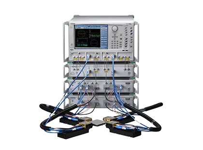
VectorStar 4-port broadband VNA system sweeping 70 kHz to 125 GHz in a single sweep with guaranteed specifications and 1 mm coaxial test ports.
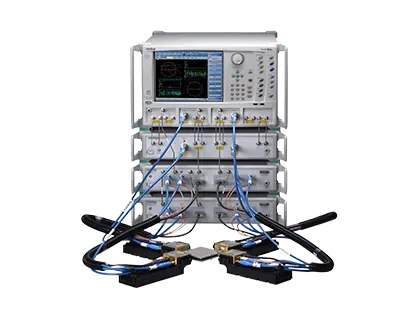
4-port broadband VNA system with single-sweep coverage from 70 kHz to 145 GHz, operational from 40 kHz to 150 GHz.