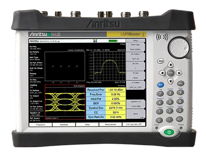
LMR Master S412E Land Mobile Radio Analyzer, Signal Generator, Spectrum Analyzer and Vector Network Analyzer
Handheld LMR test set combining a P25/DMR/TETRA/NXDN signal analyzer and generator, a 9 kHz–1.6 GHz spectrum analyzer and a 500 kHz–1.6 GHz VNA.
- Frequency Range
- 9 kHz to 1.6 GHz, (6 GHz with Option 6)
- Tuning Resolution
- 1 Hz
- Frequency Reference Aging
- ±1.0 x 10⁻⁶ per year
- Frequency Reference Accuracy
- ±1.2 x 10⁻⁷ (± 25 °C) + aging, standard; <±5.0 x 10⁻⁸ with GPS on
Overview
The Anritsu LMR Master S412E is a handheld test set for installing and maintaining land mobile radio (LMR) and professional mobile radio (PMR) systems. Built on Anritsu's ninth-generation handheld platform, it combines a receiver/spectrum analyzer, a vector network analyzer (VNA) and an LMR signal analyzer and signal generator with internally adjustable output power from 0 dBm to –130 dBm.
The instrument targets field testing of NBFM, P25, P25 Phase 2 (TDMA), DMR (MotoTRBO), TETRA, NXDN, dPMR and FDD/TDD LTE systems used in commercial, public safety, maritime and critical infrastructure networks. It also supports Positive Train Control (PTC-ITCR and PTC-ACSES) and can be configured with GSM/GPRS/EDGE measurements for GSM-R railway operators. The base model includes the VNA, the spectrum analyzer and NBFM analysis with RSSI, transmitter SINAD and THD measurements; digital radio standards, GPS-based coverage mapping, LTE and WiMAX analysis are available as options.
Cable, antenna and component test
The 500 kHz to 1.6 GHz VNA (optionally extended to 6 GHz) sweeps cables and antenna systems and performs frequency domain reflectometry distance-to-fault measurements to locate poor connections, damaged cables and water ingress. With a transmission dynamic range of up to 100 dB, it is used to adjust filters, duplexers, transmitter combiners, receiver multi-couplers and tower-mounted amplifiers. An optional internal bias tee powers tower-mounted amplifiers, and the display can emulate an Anritsu Site Master.
Spectrum and interference analysis
The spectrum analyzer covers 9 kHz to 1.6 GHz (6 GHz with Option 6) and is suited to locating low-level interfering signals near strong transmitters. Optional functions include a spectrogram recorder, interference analyzer with support for the MA2700A InterferenceHunter, channel scanner for up to 20 channels, high-accuracy power measurement with external USB sensors, vector voltmeter and PIM Hunting in conjunction with the MW82119B PIM Master.
Auto Test and Alignment
Combined with the MX281000A Auto Test and Alignment software and the MA25211A accessory kit, the S412E automates retuning and RF performance testing of Motorola APX P25 subscriber radios, with results archived to a database.
Key Features
- LMR signal analyzers with coverage mapping: P25, P25 Phase 2, DMR (MotoTRBO), TETRA, NXDN, dPMR, PTC-ITCR, PTC-ACSES, NBFM, FDD and TDD LTE
- Broadband signal analyzers: LTE, WiMAX
- Interference analyzer with interference mapping and support for MA2700A Handheld InterferenceHunter
- Auto Test and Alignment of Motorola APX P25 mobiles and portables
- Direct measurement of up to 150 watt transmitters
- Spectrum analyzer: 9 kHz – 1.6 GHz, optional to 6 GHz
- Cable and antenna analyzer: 500 kHz – 1.6 GHz, optional to 6 GHz
- Return Loss, VSWR, Insertion Loss, S11 / S21, DTF
- PIM Hunting
- Internal power meter, optional external power sensor
- Internal signal generator with 0.1 dB resolution, 0 dBm to –130 dBm
- Duplex test: simultaneous analysis and generation of analog or digital LMR signals
- Handheld, battery-operated design
- Rugged design on Anritsu's 9th generation hardware platform
- 8.4 inch daylight-viewable color touchscreen display
- Immunity to RF interference
- Remote control via Ethernet
- Standard three-year warranty (battery one-year warranty)
Specifications
| Frequency Range | 9 kHz to 1.6 GHz, (6 GHz with Option 6) |
|---|---|
| Tuning Resolution | 1 Hz |
| Frequency Reference Aging | ±1.0 x 10⁻⁶ per year |
| Frequency Reference Accuracy |
±1.2 x 10⁻⁷ (± 25 °C) + aging, standard; <±5.0 x 10⁻⁸ with GPS on
GPS value 3 minutes after satellite is locked in selected mode
|
| Frequency Span | 10 Hz to 1.6 GHz including zero span (10 Hz to 6 GHz with Option 6) |
| Sweep Time | 100 ms min, 7 μs to 3600 seconds in zero span |
| Sweep Time Accuracy | ± 2% in zero span |
| Resolution Bandwidth (RBW) |
10 Hz to 3 MHz in 1–3 sequence ± 10%
1 MHz max in zero span; –3 dB bandwidth
|
| Video Bandwidth (VBW) |
1 Hz to 3 MHz in 1–3 sequence
–3 dB bandwidth; auto or manually selectable
|
| RBW with Quasi-Peak Detection |
200 Hz, 9 kHz, 120 kHz
–6 dB bandwidth
|
| SSB Phase Noise @ 1 GHz, 10 kHz offset | –100 dBc/Hz, –110 dBc/Hz typical |
|---|---|
| SSB Phase Noise @ 1 GHz, 100 kHz offset | –105 dBc/Hz, –112 dBc/Hz typical |
| SSB Phase Noise @ 1 GHz, 1 MHz offset | –115 dBc/Hz, –121 dBc/Hz typical |
| Dynamic Range |
> 95 dB (2.4 GHz)
2/3 (TOI-DANL) in 10 Hz RBW
|
| Measurement Range | DANL to +26 dBm (≥ 50 MHz); DANL to 0 dBm (< 50 MHz) |
| RF In Port Damage Level |
+33 dBm peak, ± 50 VDC
Maximum continuous input (≥ 10 dB attenuation)
|
| Display Range | 1 to 15 dB/div in 1 dB steps, ten divisions displayed |
| Reference Level Range | –150 dBm to +30 dBm |
| Attenuator Resolution | 0 to 55 dB, 5.0 dB steps |
| Amplitude Accuracy, 9 kHz to 100 kHz |
± 2.0 dB typical (Preamp Off)
Single sine wave, input power < Ref level and > DANL, Attenuation: Auto, Ambient: –10 °C to 50 °C after 30 minute warm-up
|
| Amplitude Accuracy, > 100 kHz to 4.0 GHz | ± 1.25 dB, ± 0.5 dB typical |
|
Amplitude Accuracy, > 4.0 GHz to 6 GHz
S412E-0006
|
± 1.50 dB, ± 0.5 dB typical |
| DANL, 10 MHz to 2.4 GHz (RBW = 10 Hz, Preamp On) |
–147 dBm maximum, –152 dBm typical
0 dB attenuation, reference level –50 dBm
|
| DANL, 10 MHz to 2.4 GHz (RBW = 10 Hz, Preamp Off) |
–131 dBm maximum, –136 dBm typical
0 dB attenuation, reference level –20 dBm
|
| Residual Spurious |
< –90 dBm
RF input terminated, 0 dB input attenuation, > 10 MHz
|
| Input-Related Spurious |
< –75 dBc
0 dB attenuation, –30 dBm input, span < 1.7 GHz, carrier offset > 4.5 MHz
|
| Third-Order Intercept (TOI), 800 MHz |
+16 dBm
Preamp Off, –20 dBm tones, 100 kHz apart, 10 dB attenuation
|
| Third-Order Intercept (TOI), 2400 MHz |
+20 dBm
Preamp Off, –20 dBm tones, 100 kHz apart, 10 dB attenuation
|
| Second Harmonic Distortion, 50 MHz |
–56 dBc
Preamp Off, 0 dB input attenuation, –30 dBm input
|
| VSWR | 2:1 typical |
| Architecture | 1-path, 2-port Vector Network Analyzer (VNA) with quad trace display |
|---|---|
| Frequency Range | 500 kHz to 1.6 GHz (500 kHz to 6.0 GHz with Option 16) |
| Frequency Accuracy | 2.5 ppm |
| Frequency Resolution | 1 Hz |
| Transmission Dynamic Range, 2 MHz to ≤ 4 GHz |
100 dB
10 Hz IF Bandwidth and High Port Power
|
|
Transmission Dynamic Range, 4 GHz to ≤ 6 GHz
S412E-0016
|
90 dB
10 Hz IF Bandwidth and High Port Power
|
| Test Port Power, 500 kHz to ≤ 3 GHz (typical) | +3 dBm High, –5 dBm Default, –25 dBm Low |
|
Test Port Power, 3 GHz to ≤ 6 GHz (typical)
S412E-0016
|
0 dBm High, –5 dBm Default, –25 dBm Low |
| Typical Sweep Speed |
850 μs / point
IF Bandwidth of 100 Hz, 1001 data points, single display
|
| Typical Noise Floor | –100 dBm (500 kHz to 3 GHz); –103 dBm (3 GHz to 4 GHz); –93 dBm (4 GHz to 6 GHz) |
| Temperature Stability (typical) |
0.020 dB/ºC magnitude, 0.200 deg/ºC phase
S11 or S21, Short, 23 ºC ± 5 ºC, 500 kHz to 6 GHz
|
| Interference Immunity, On-Channel | +17 dBm at > 1.0 MHz from carrier frequency |
| Interference Immunity, On-Frequency | 0 dBm within ± 10 kHz of the carrier frequency |
| Measurement Parameters | S11, S21 |
| Graph Types | Log Magnitude, SWR, Phase, Real, Imaginary, Group Delay, Smith Chart, Log Mag/2 (1-Port Cable Loss), Linear Polar, Log Polar, Real Impedance, Imaginary Impedance |
| Data Points |
2 to 4001 (arbitrary setting)
Data points can be reduced without recalibration
|
| IF Bandwidth | 10, 20, 50, 100, 200, 500, 1 k, 2 k, 5 k, 10 k, 20 k, 50 k, 100 k (Hz) |
| Number of Markers | 12, arbitrary assignments to any trace |
| Calibration Methods | Short-Open-Load-Through (SOLT) |
| Directivity (corrected, N-Type) |
≥ 42 dB
High port power, OSLN50A-8/OSLNF50A-8/TOSLN50A-8/TOSLNF50A-8 calibration kit
|
| Source Match (corrected, N-Type) | ≥ 30 dB |
| Calibration Stability | up to 16 hours |
| Maximum Distance (4001 data points, 1.6 GHz span) | 374.9 m (1,229.9 ft) |
|---|---|
|
Maximum Distance (4001 data points, 6.0 GHz span)
S412E-0016
|
99.9 m (327.75 ft) |
| Minimum Distance Resolution (1.6 GHz span) | 18.7 cm (7.36 in) |
|
Minimum Distance Resolution (6.0 GHz span)
S412E-0016
|
4.99 cm (1.97 in) |
| Measurement Display | Return Loss, VSWR |
|
Frequency Range
S412E-0010
|
2 MHz to 4/6 GHz at VNA Port 2 |
|---|---|
|
Internal Voltage/Current
S412E-0010
|
+12 V to +32 V at 450 mA (Steady state)
Bias available on VNA Port 2 and the SPA Input (RF In)
|
|
Internal Resolution
S412E-0010
|
0.1 V |
|
CW Frequency Range
S412E-0015
|
500 kHz to 1.6 GHz (6 GHz with Option 16) |
|---|---|
|
Measurement Display
S412E-0015
|
CW, Table (Twelve Entries, Plus Reference) |
|
Measurement Format
S412E-0015
|
dB/VSWR/Impedance |
| Frequency Range | 500 kHz to 1.6 GHz |
|---|---|
| Tx Output Level | 0.1 dB resolution, 0 dBm to –130 dBm (spec to –120 dBm) |
| Power Level Accuracy |
2.0 dB typical
CW Pattern, temperature range 15 °C to 35 °C, –120 dBm to 0 dBm
|
| CW Tx Pattern | CW, AM w/ 1 kHz, FM w/ 1 kHz |
| FM / AM Modulation | FM, 100 Hz to 10 kHz rate, adjustable deviation; AM, 100 Hz to 10 kHz rate, adjustable depth |
|
P25 Modulation Fidelity
S412E-0521
|
< 1.25 % max, < 0.75 % typical |
|
P25p2 Modulation Fidelity
S412E-0521
|
< 2.0 % max, < 1.75 % typical |
|
DMR Mod Fidelity
S412E-0591
|
1.25 % max, 0.75 % typical |
|
NXDN Mod Fidelity
S412E-0531
|
1.25 % max |
|
TETRA EVM
S412E-0581
|
3.5 % max |
|
PTC-ITCR EVM
S412E-0721
|
3.5 % max |
| Received Power |
dBm ± 1.25 dB, ± 0.5 dB typical
Temperature range 15 °C to 35 °C; NBFM, P25, DMR, dPMR, NXDN, TETRA, PTC analyzers
|
|---|---|
| Frequency Error | Hz ± 10 Hz + Frequency Reference |
|
P25 SINR
S412E-0521
|
± 1.5 dB from 10 to 25 dB; ± 2.0 dB from 0 to 10 dB and 25 to 30 dB |
|
P25 Standards Compliance
S412E-0521
|
Relevant sections of TIA-102.CAAA-C (P25), TIA-102.CCAA (P25 Phase 2) |
| NBFM Tone Decode | CTCSS/DCS (standard tones per TIA-603-D), DTMF |
| Internal Power Meter Frequency Range | 10 MHz to 1.6 GHz (Standard), 10 MHz to 6 GHz (Option 6) |
|---|---|
| Internal Power Meter Span | 1 kHz to 100 MHz |
| Internal Power Meter Display Range | –140 dBm to +30 dBm, ≤ 40 dB span |
| Internal Power Meter Measurement Range | –120 dBm to +26 dBm |
|
High Accuracy Power Meter Sensors
S412E-0019
|
MA24103A/105A, MA24106A, MA24108A/18A/26A, MA24208A/18A, MA24330A/40A/50A
Requires external USB power sensor, sold separately
|
|
Number of Channels
S412E-0027
|
1 to 20 Channels |
|---|---|
|
Frequency Accuracy
S412E-0027
|
± 10 Hz + Frequency Reference |
|
Measurement Range
S412E-0027
|
–110 dBm to +26 dBm |
|
Spectrogram
S412E-0025
|
Collect data up to 72 hours |
|---|---|
|
Signal ID
S412E-0025
|
Up to 12 signals
Signal type: FM, GSM, W-CDMA, CDMA, Wi-Fi
|
|
GPS-Enhanced Frequency Accuracy
S412E-0031
|
< 50 ppb with GPS On
3 minutes after satellite is locked in selected mode
|
|---|---|
|
GPS Connector
S412E-0031
|
SMA, Female
Requires external GPS antenna, sold separately
|
|
GPS Antenna Voltage
S412E-0031
|
3.3/5.0 V |
| Ethernet Connector | RJ45 |
| LAN Speed | 10 Mbps |
| Remote Control | Web Remote Control and SCPI programming |
| Display |
8.4 inch daylight-viewable TFT LCD color resistive touchscreen
Allows use while wearing gloves
|
|---|---|
| Battery Operation Time | 3 hours |
| Size | 273 mm x 199 mm x 91 mm, (10.7 in x 7.8 in x 3.6 in) |
| Weight |
3.6 kg, (7.9 lb)
Product page states less than 7.6 lb (including battery); datasheet value used
|
| Environmental Compliance |
Complies with MIL-PRF-28800F Class 2 and MIL-STD-810G
Certified for use in explosive atmosphere per MIL-PRF-28800F
|
| Languages | English, French, German, Spanish, Chinese, Japanese, Korean, Italian, Russian, and Portuguese |
| Warranty | Standard three-year warranty (battery one-year warranty) |
Specifications are taken from the manufacturer's documentation. See the datasheet for complete and current values.
Applications
- Field analysis and coverage mapping of P25, DMR, TETRA, NXDN, dPMR and PTC radio systems
- Public safety, government, commercial and critical infrastructure radio networks
- Railway Positive Train Control (ITCR and ACSES) and GSM-R
- LTE and WiMAX broadband and intersite backhaul measurements
- Spectrum and interference analysis
- Cable and antenna sweeping and distance-to-fault
- Filter, duplexer, combiner and tower-mounted amplifier tuning
- Occupied bandwidth and emission mask compliance testing
- Narrowband FM transmitter analysis
- RF power measurement of CW and modulated signals
- Indoor and outdoor coverage mapping
- Automated test and alignment of Motorola APX radios
Included
- Data analysis software
- Soft carrying case
- Rechargeable/field-replaceable battery
- AC/DC power supply
- 12V automobile cigarette lighter adapter
- User's Guide
Options & Accessories
| Option | Description |
|---|---|
| S412E-0010 | 12 to 24V Variable Bias Tee — Integrated bias tee for applications where both DC and RF signals must be applied to a device under test, such as a tower mounted amplifier (TMA). |
| S412E-0006 | 6 GHz Coverage on Spectrum Analyzer |
| S412E-0016 | 6 GHz Coverage on Vector Network Analyzer |
| S412E-0015 | Vector Voltmeter |
| S412E-0019 | High Accuracy Power Meter (requires PSN50 sensor) — The PSN50 sensor makes high accuracy power measurements from 50 MHz to 6 GHz. |
| S412E-0025 | Interference Analysis — Spectrogram provides a three-dimensional display of frequency, power, and time; RSSI measurement observes the signal strength of a single frequency over time. |
| S412E-0027 | Channel Scanner — Measures the power of multiple transmitted signals. |
| S412E-0031 | GPS Receiver (requires suitable GPS antenna) — Provides location (latitude, longitude, altitude) and UTC time information; traces can be stamped with location information. |
| S412E-0037 | Mobile WiMAX OTA Measurements — Option 31 required for full functionality |
| S412E-0046 | Fixed WiMAX RF Measurements |
| S412E-0047 | Fixed WiMAX Demodulation |
| S412E-0066 | Mobile WiMAX RF Measurements |
| S412E-0067 | Mobile WiMAX Demodulation |
| S412E-0431 | Coverage Mapping — Requires Option 0031 |
| S412E-0444 | EMF Measurements — Requires Anritsu Isotropic Antenna |
| S412E-0509 | AM/FM/PM Analyzer with Coverage Mapping — Options 0031 and 0431 are required for utilization of coverage mapping feature |
| S412E-0521 | P25 & P25 Phase 2 Analyzer |
| S412E-0522 | P25 & P25 Phase 2 Coverage Mapping — Requires Options 0031 and 0521 |
| S412E-0531 | NXDN Analyzer |
| S412E-0532 | NXDN Coverage Mapping — Requires Options 0031 and 0531 |
| S412E-0541 | LTE RF Measurements — Requires Option 0031 |
| S412E-0542 | LTE Modulation Quality — Requires Option 0031 |
| S412E-0546 | LTE OTA Measurements — Option 31 required for full functionality |
| S412E-0551 | TDD LTE RF Measurements — Requires Option 541 |
| S412E-0552 | TDD LTE Modulation Quality — Requires Option 542 |
| S412E-0556 | TDD LTE OTA Measurements — Options 31 & 546 required for full functionality |
| S412E-0886 | 256 QAM Demodulation for LTE Modulation Quality — Requires Option 542 |
| S412E-0572 | dPMR Coverage Mapping — Requires Options 573 and 31 |
| S412E-0573 | dPMR Analyzer |
| S412E-0581 | TETRA Analyzer |
| S412E-0582 | TETRA Coverage Mapping |
| S412E-0591 | DMR2 Analyzer |
| S412E-0592 | DMR2 Coverage Mapping — Requires Options 0031 and 0591 |
| S412E-0721 | PTC-ITCR Analyzer |
| S412E-0722 | PTC-ITCR Coverage Mapping — Requires Options 0031 and 0721 |
| S412E-0731 | PTC-ACSES Analyzer |
| S412E-0733 | PTC-ACSES Coverage Mapping — Requires Options 0031 and 0731 |
| S412E-0880 | GSM/GPRS/EDGE Measurements |
| S412E-0098 | Standard Calibration (ANSI Z540-1-1994) |
| S412E-0099 | Premium Calibration (ANSI Z540-1-1994 plus test data) |
| MX281000A-0100 | Auto Test and Align for Motorola APX 6/7/8x00 Radios (Dongle) |
| MX281000A-0110 | Auto Test and Align for Motorola APX NEXT Radios (Dongle) |
| MX281000A-0101 | Auto Test and Align for Motorola APX 6/7/8x00 Radios (Node Locked) |
| MX281000A-0111 | Auto Test and Align for Motorola APX NEXT Radios (Node Locked) |
| MA25211A | Auto Test and Alignment Kit — Accessory kit used with MX281000A software for automated testing of Motorola P25 subscriber units. |
Documents & Resources
Related Products
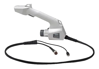
Handheld direction finding system with built-in GPS receiver, electronic compass and preamplifier for interference mapping with Anritsu analyzers.
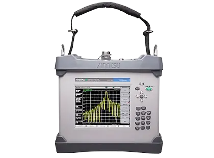
Battery-operated 40 W portable PIM analyzer with optional Site Master cable and antenna analyzer for field certification of cell sites.