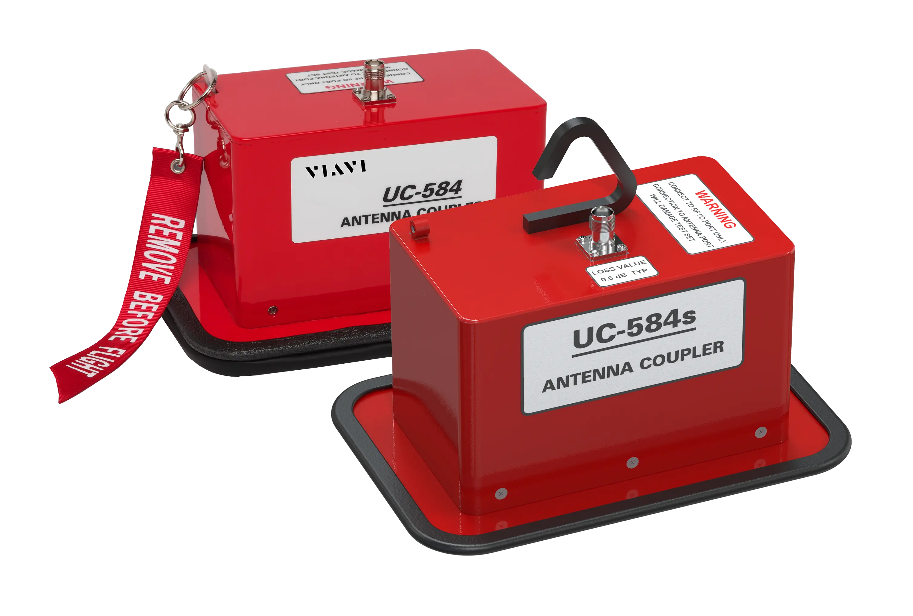
VIAVI UC-584S Top Mount Transponder Antenna Coupler
Top mount L-Band transponder antenna coupler placed on the upper antenna with a pole, providing >20 dB isolation for ERP and MTL tests
- Frequencies
- 1030 MHz, 1090 MHz
- Return Loss
- >7.71 dB
- Insertion Loss
- 0.6 dB ±0.5 dB
- Repeatability
- <1 dB
Overview
The VIAVI UC-584 Series Transponder Antenna Couplers address reliable FAR Part 43 Appendix 'F' ERP (Effective Radiated Power) and transponder MTL (Minimum Trigger Level) testing in high multi-path ramp and hangar environments. The coupler fits over the aircraft L-Band transponder antenna and includes an integral positioning slot that supports a high level of measurement repeatability.
The couplers provide more than 20 dB of attenuation, which minimizes the chance that airborne TCAS systems and air traffic controllers see transponder altitude replies from the unit under test during testing. They also provide shielding for ADS-B performance testing and UUT parametric tests. Effectiveness depends on the distance of the ADS-B ground station from the test site and on any shielding in the hangar.
The series comprises the UC-584, which uses a clamping mechanism to secure the coupler to the bottom antenna, and the UC-584S, which is placed onto the top antenna from the ground or a ladder using a pole. The couplers can be connected to the VIAVI IFR6000, IFR6015 and APM-424(V)5 flight line test sets, the VIAVI IFF-45TS bench test set, or any suitable transponder test set.
Key Features
- Reliable FAR Part 43 Appendix 'F' ERP and MTL testing in high multi-path environments
- Provides >20 dB of antenna isolation for Mode S transponder altitude and diversity tests
- Provides shielding for ADS-B performance testing UUT parametric tests
- Reduces interference with air traffic control and nearby aircraft
- Integral positioning slot for repeatable measurements
- Dual antenna kit configuration
- Rugged design for ramp use
- Fits most 'Shark Fin' L-Band antennas
- Universal design allows use with any suitable transponder test set
- Hook for easy top mount, pole placement
- Design eliminates the need to climb onto the aircraft for placement
- Can be placed over the upper antenna from the ground or scaffolding
Specifications
| Frequencies | 1030 MHz, 1090 MHz |
|---|---|
| Return Loss |
>7.71 dB
at both the antenna under test input and coupler input
|
| Insertion Loss |
0.6 dB ±0.5 dB
typical
|
| Repeatability | <1 dB |
| Isolation | >20 dB |
| Connector | TNC Female |
| Dimensions |
8.2 in x 5.75 in x 5.25 in (20.9 cm x 14.6 cm 13.3 cm)
Web page lists depth as 8.25 inches (20.9 cm)
|
|---|---|
| Weight | 2 lbs (0.9 kg) |
| Width | 3.9 in (9.9 cm) |
|---|---|
| Thickness | 0.25 in. (0.635 cm) |
| Height | 3.75 in. (9.52 cm) |
Specifications are taken from the manufacturer's documentation. See the datasheet for complete and current values.
Applications
- FAR Part 43 Appendix 'F' ERP testing
- Transponder MTL testing
- Mode S transponder altitude and diversity tests
- ADS-B performance testing
- Ramp and hangar avionics testing
Options & Accessories
| Option | Description |
|---|---|
| 90106 | Kit, Antenna Coupler Pole, 8 ft. w/ D Ring — Optional accessory |
| 142094 | UC-584S Top Mount Transp. Antenna Coupler — Ordered separately or included with the UC-584 dual antenna Coupler Kit (112349) |
Documents & Resources
Related Products
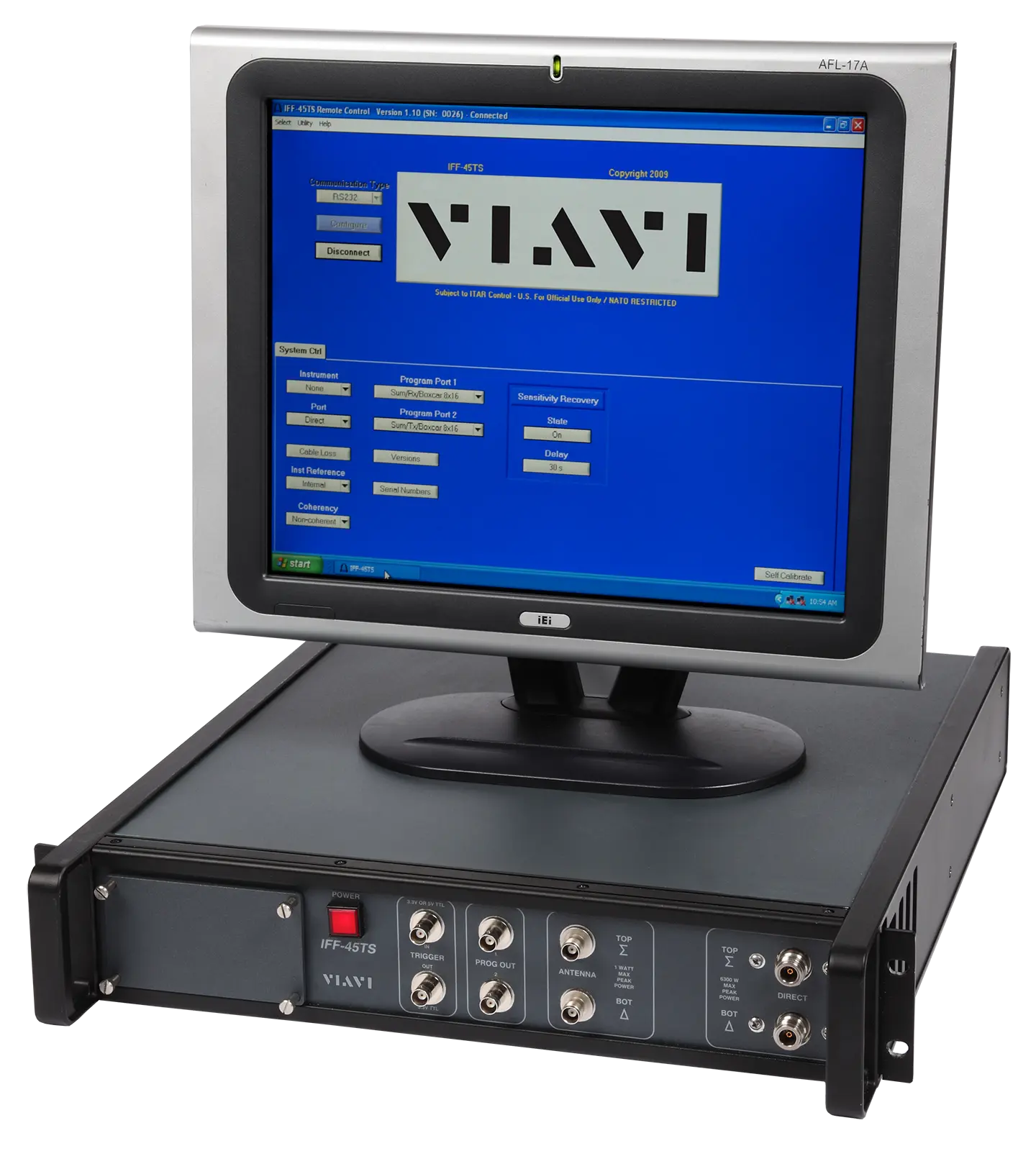
Remote-controlled RF bench test set for signal generation and parametric measurement of MK XIIA transponders, interrogators and TACAN equipment.
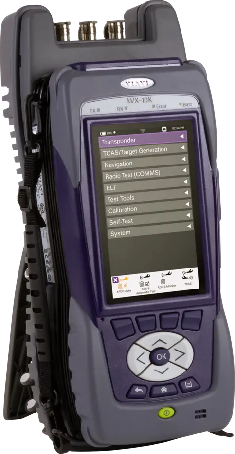
Handheld avionics flight line test set covering transponder, ADS-B, UAT, TCAS, NAV/COMM, DME/TACAN, ELT and VSWR/DTF testing in one device.
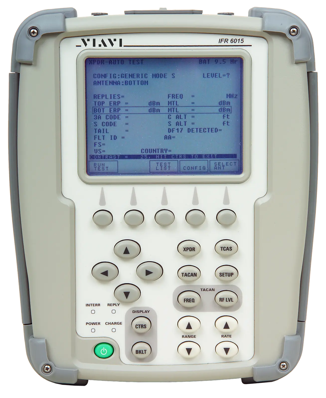
Portable flight line test set for IFF/Mode S transponders, TCAS/E-TCAS, UAT and DME/TACAN, with IFF Modes 1, 2 and TACAN standard.