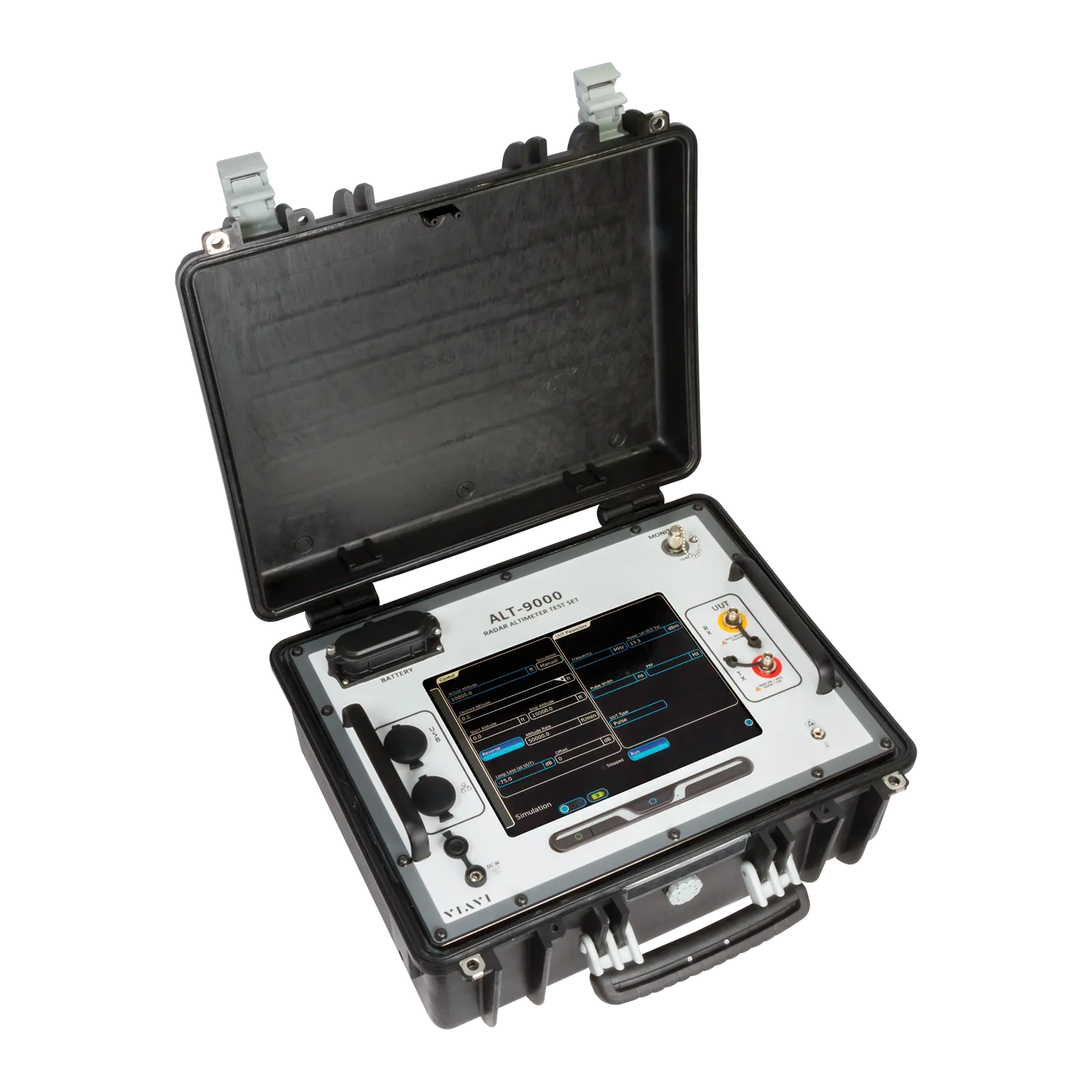
VIAVI ALT-9000 Radio Altimeter Test Set – Universal Flight Line Test Solution
Portable radio altimeter test set with fiber optic delay line, simulating altitudes from 5 to 10,000 ft for FMCW and pulse altimeters.
- Display
- 12” color LCD, sun light readable w/back light
- Controls
- Touch-screen
Overview
The VIAVI ALT-9000 is a radio altimeter test set for flight line and benchtop use. It provides altitude simulations with true RF time delay and path loss models, allowing it to test any format of radio altimeter system, including Low Probability of Intercept (LPI), Combined Altitude Radar Altimeter (CARA) and next-generation variants.
The test set is based on a fiber optic delay line and simulates static altitudes from 5 ft to 10,000 ft in 5 ft increments; the minimum altitude depends on the interconnecting cables. An extended range option adds 16,000 ft and 25,000 ft as discrete altitude selections.
A graphical touch-screen interface provides the controls and displays parametric measurements including TX power, TX frequency, FM deviation, sweep rate, pulse width and PRF. The unit connects directly to the unit under test T/R ports or to an installed system via antenna couplers, with automatic compensation for test cables, coupler loss and external attenuation.
The ALT-9000 is housed in a portable ruggedized enclosure and is battery operated, with an external AC to DC converter supplied for indoor use.
Key Features
- Fiber optic delay line based test set supports all formats of radio altimeters
- Altitude simulation with true RF time delay and path loss models
- Tests LPI, CARA and next-generation radio altimeter variants
- Portable ruggedized enclosure for flight line or benchtop use
- Battery operated
- Simulates static altitudes from 5 ft to 10,000 ft in 5 ft increments (minimum altitude dependent on interconnecting cables)
- Extended Range Option: simulate 16,000 ft and 25,000 ft as discrete altitude selections
- +20 dB of power level offset from nominal loop loss value
- Touch-screen operation
- Direct-connect to UUT T/R or installed system via antenna couplers
- Measures TX power, TX frequency, FM deviation, sweep rate, pulse width and PRF
Specifications
| Display | 12” color LCD, sun light readable w/back light |
|---|---|
| Controls | Touch-screen |
| Impedance | 50 Ω |
|---|---|
| SWR (TX) | 2.0:1 |
| SWR (RX) | 1.5:1 |
| Connector | TNC x 2 (single TX/RX channel) |
| RF Input Frequency Range | 4.20 GHz to 4.40 GHz |
|---|---|
| Frequency Measurement Range | 4.20 GHz to 4.40 GHz |
| Frequency Measurement Accuracy | ±5 MHz |
| TX Power Measurement Range | 4 mW (+6 dBm) to 2 W (+33 dBm) |
| TX Power Measurement Accuracy |
+2 dB
As printed in the datasheet
|
| FM Sweep Rate Measurement Range | 50 Hz to 400 Hz |
| FM Sweep Rate Measurement Accuracy | ±5 Hz |
| FM Deviation Range | ±20 MHz to 100 MHz |
| FM Deviation Accuracy | ±5 MHz |
| Frequency Measurement Range | 4.20 GHz to 4.40 GHz |
|---|---|
| Frequency Measurement Accuracy | ±10 MHz |
| TX Power Measurement Range | 1 mW (0 dBm) to 300 W (+54 dBm) peak |
| TX Power Measurement Accuracy |
±2 dB
>50 ns
|
| TX Power Measurement Accuracy |
±3 dB
<50 ns
|
| TX Pulse Width Measurement Range | 20 ns to 5 µs |
| TX Pulse Width Measurement Accuracy | ±10 ns |
| TX Pulse PRF Measurement Range | 2 KHz to 30 KHz |
| TX Pulse PRF Measurement Accuracy | ±5% |
| Range | 1 to 120,000 fpm |
|---|---|
| Altitude Update Rate | 10 Hz max |
| Attenuation |
-46 dBc typical
At carrier frequency
|
|---|
| Test Cable Length |
1 to 25 ft
Automatic compensation
|
|---|---|
| Test Cable Loss |
0 to 9.9 dB
Automatic compensation
|
| Antenna Couplers | TX and RX |
| Coupler Loss Compensation | 0 to 19.9 dB |
| External Attenuation Range |
0 to 20 dB (UUT:TX), 0 to 50 dB (UUT:RX)
Automatic compensation
|
| Range |
5 to 10,000 ft
At test set connectors, plus interconnecting cables. Minimum simulated altitude will be 5ft + test cable delay + Altitude Offset setting
|
|---|---|
| Optional Range |
16,000 and 25,000 ft as discrete altitude selections
Extended Range Option
|
| Resolution |
5 ft
Standard range only
|
| Accuracy | ±1ft. ±1% of simulated altitude |
| Altitude Switching Time |
5ms max
Typically < 3ms
|
| Altitude Offset | -100 to 100 ft |
| Manual Mode Range |
-35 to -135 dB (0 to 50 ft)
Dependent upon cable loss, coupler loss and external attenuation; altitude with 0 ft Altitude Offset
|
|---|---|
| Manual Mode Range |
-55 to -135 dB (55 to 5000 ft)
Dependent upon cable loss, coupler loss and external attenuation; altitude with 0 ft Altitude Offset
|
| Manual Mode Range |
-60 to -135 dB (>5000 ft)
Dependent upon cable loss, coupler loss and external attenuation; altitude with 0 ft Altitude Offset
|
| Manual Mode Accuracy | ±2 dB -35 to -95 dB @ 4.30 GHz |
| Manual Mode Accuracy | ±3 dB -95 to -135 dB @ 4.30 GHz |
| Flatness |
±2 dB typical
4.20 to 4.40 GHz, referenced to 4.30 GHz
|
| Auto Mode | Computed path loss based on altitude, scattering, cables, couplers and offset |
| RF Level Offset (auto) | -20 to +20 dB |
| Frequency Stability | ±1 ppm |
| DC Input Voltage | 11-32 VDC |
|---|---|
| DC Input Power | 75 w max |
| DC Input Current | 5 A max |
| Battery Life |
>4 Hrs continuous
At 25°C
|
| AC to DC Converter AC Input Power |
100-240 VAC 50/60 Hz
Supplied external AC to DC converter (indoor use)
|
| Test Set Operating Temperature | -10° to 55°C (14° to 131°F) |
|---|---|
| Test Set Storage Temperature |
-51° to 71°C (-59.8° to 159.8°F)
With battery removed
|
| AC to DC Converter Operating Temperature | 5° to 40°C (41° to 104°F) |
| AC to DC Converter Storage Temperature | -20° to 71°C (-4° to 159.8°F) |
| AC to DC Converter Altitude | <10,000 feet |
| Size (test set case) | 8.5 in H x 18.7 in W x 16.4 in D (21.6 cm x 47.5 cm x 41.7 cm) |
|---|---|
| Size (w/standard transit case, or accessory case) | 16.25 in H x 33.75 in W x 28.5 in D (41.3 cm x 85.8 cm x 72.4 cm) |
| Weight (test set only) | 32 lbs, 14.52 kg |
| Weight (kit) | 88 lbs, 39.92 kg |
| Operating Temperature | MIL-PRF-28800, Class 2 |
|---|---|
| Storage Temperature | MIL-PRF-28800F, Class 2 |
| Operational and Storage Humidity | MIL-PRF-28800F, Class 2 |
| Vibration Limits | MIL-PRF-28800F, Class 2 |
| Shock, Functional and Resistance | MIL-PRF-28800F, Class 2 |
| Transit Drop |
MIL-PRF-28800F, Class 2
Tests to be performed with unit in transit case and lid closed
|
| Bench Handling | MIL-PRF-28800F, Class 2 |
| Watertight / Drip Proof | MIL-PRF-28800F, Class 2 |
| Sand Dust |
MIL-PRF-28800F, Class 2
Tests to be performed with unit in transit case and lid closed
|
| Salt Atmosphere |
MIL-PRF-28800F, Class 2
Tests to be performed with unit in transit case and lid closed
|
| Explosive Atmosphere | MIL-STD-810F, Method 511.4 |
| Solar Radiation | MIL-PRF-28800F, Class 2 |
| Safety Compliance (test set) | EN/UL-61010-1, 3rd Edition |
| Environmental Directives | WEEE, ROHS |
| EMC (test set) | EN/IEC 61326-1: 2013 |
| AC-DC Converter Safety Compliance | UL 1950 DS, CSA 22.2 No. 234, VDE EN 60 950 |
| AC-DC Converter EMI/RFI Compliance | FCC Docket 20780 Curve “B” |
| AC-DC Converter EMC | EN 61326 |
Specifications are taken from the manufacturer's documentation. See the datasheet for complete and current values.
Applications
- Radio altimeter flight line testing
- Radio altimeter bench troubleshooting
- LPI radio altimeter testing
- CARA radio altimeter testing
- 5G interference investigation on radio altimeters
Included
- External AC to DC converter (indoor use)