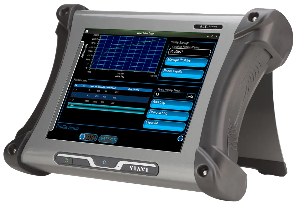
VIAVI ALT-8000 FMCW/Pulse Radio Altimeter Flight Line Test Set
Portable RF-based flight line test set for installed 4.3 GHz FMCW and pulse radio altimeters, with a 12-inch color touch-screen.
- Display
- 12” color LCD, sun light readable with back light
- Controls
- Touch-screen
- Remote control interface
- USB/LAN
Overview
The VIAVI ALT-8000 is a portable, RF-based flight line test set for radio altimeters. It is a universal test set for 4.3 GHz FMCW (frequency modulated continuous wave) radio altimeters and pulse radio altimeters. It has a 12-inch color touch-screen, and its software can be upgraded. For military applications, VIAVI offers the ALT-8015.
The ALT-8000 tests the whole installed system, from the antenna to the indicator in the cockpit. This lets the operator replicate in-flight conditions and isolate a faulty component of the installed system.
User Interface
The user interface is Windows-based. Its pages control the test set and display parametric measurements, including TX power, TX center frequency, sweep rate and TX pulse width (pulse systems). On the setup page, the user sets system, user and RF connection parameters, including RS-232, AID, RF cable loss and altitude offset.
Profiles
On the Profile page, users can create, save, recall or delete named profiles. Each profile is made up of individual legs, and start altitude, stop altitude and rate can be set for each leg. Running a profile can simulate a complete landing approach, including the flare out, or a take-off and departure.
RF Coupling
The supplied antenna couplers allow quick verification of the radio altitude system without access to test ports on the UUT LRU. The RF looped test verifies TX frequency, power and sweep rate. RF level control is used to test UUT sensitivity.
Key Features
- Tests FMCW radio altimeters including CDF types
- Tests pulse radio altimeters (non-pulse compression types)
- Direct-connect to UUT T/R or to installed system via antenna couplers
- Full RF loop test allows TX, RX, Antenna or Feeder faults to be identified
- Multi-channel operation (via additional test sets)
- Programmable multi-leg climb/descend profiles
- Large touch-screen display with simple user interface
- Remote control interface USB/LAN
- Battery 4 hours plus duration
- Tests from the antenna to the cockpit indicator to replicate in-flight conditions
- Windows-based user interface with parametric measurement display
- Software upgradable
Specifications
| Display | 12” color LCD, sun light readable with back light |
|---|---|
| Controls | Touch-screen |
| Remote control interface | USB/LAN |
| Couplers | TX and RX |
|---|---|
| Coupler Loss Compensation | 0 to 19.9 dB |
| Impedance | 50 Ω |
|---|---|
| SWR TX | 2.5:1 |
| SWR RX | 3:1 |
| Connector | TNC x 2 (single TX/RX channel) |
| RF Input Frequency Range |
4.20 to 4.40 GHz
ITAR Limited
|
|---|---|
| Frequency Measurement Range |
4.20 to 4.40 GHz
ITAR Limited
|
| Frequency Measurement Accuracy | ±5 MHz |
| RF TX Power Input Tracking Range | 10 mW (+10 dBm) to 2 W (+33 dBm) |
| RF TX Power Measurement Range | 4 mW (+6 dBm) to 2 W (+33 dBm) |
| RF TX Power Measurement Accuracy | ±2 dB |
| FM Sweep Rate Measurement Range | 50 to 400 Hz |
| FM Sweep Rate Measurement Accuracy | ±5 Hz |
| FM Deviation Range | 20 to 100 MHz |
| Frequency Measurement Range |
4.20 to 4.40 GHz
ITAR Limited
|
|---|---|
| Frequency Measurement Accuracy | ±10 MHz |
| Power Measurement Range | 1 W (+30 dBm) to 300 W (+54 dBm) peak |
| Power Measurement Accuracy | ±2 dB |
| TX Pulse Width Measurement Range | 20 ns to 400 ns |
| TX Pulse Width Measurement Accuracy | ±10ns |
| TX Pulse PRF Measurement Range | 2 to 30 KHz |
| TX Pulse PRF Measurement Accuracy | ±5% |
| FMCW Linear Altitude Simulation Range | -20 to 5,500 ft |
|---|---|
| FMCW Linear Altitude Simulation Resolution | 1 ft. increments |
| FMCW Linear Altitude Simulation Accuracy |
±1.5 ft or 2% RMS
(-20 to 5,500 ft), whichever is greater
|
| Pulse Linear Altitude Simulation Range |
50 to 5,500 ft
Lower altitude limit determined by connecting RF coax cable length
|
| Pulse Linear Altitude Simulation Resolution | 1 ft increments |
| Pulse Linear Altitude Simulation Accuracy |
±1.5 ft or 2% RMS
whichever is greater
|
| Linear Altitude Rate Range | 1 to 10,000 fpm |
| Linear Altitude Rate Resolution | 1 ft. increments |
| Test Cable Length |
1 to 100 ft
Automatic compensation
|
| Test Cable Loss |
0 to 9.9 dB
Automatic compensation
|
| AID (direct connect) Fixed Selectable | 0, 20, 40, 57 or 80 ft |
| AID (direct connect) User Entered | 0 to 99 ft |
| Altitude Offset | -25 to 100 ft |
| RF Path Loss Simulation | 0 to 5,500 ft |
| Frequency Stability | ±1 ppm |
| Manual Mode (FM/CW) Range |
-84 to +9 dBm
Varies with cable loss
|
|---|---|
| Manual Mode (FM/CW) Accuracy | ±4 dB |
| Manual Mode (Pulse) Range | -76 to +17 dBm |
| Manual Mode (Pulse) Accuracy | ±4 dB |
| Auto Mode | TX Power – Height Path Loss- Scattering Loss- Offset |
| RF Level Offset (auto) | -20 to +20 dB |
| Operational Temperature | -20° to 55°C (-4° to 131°F) |
|---|---|
| Storage Temperature | -30° to 71°C (-22° to 159.8°F) |
| Altitude | ≤10,000 meters |
| Dimensions, test set only (H x W x D) | 10.6 x 13.9 x 3.4 in (27.0 x 35.5 x 8.7 cm) |
|---|---|
| Dimensions, with standard accessories (H x W x D) | 12 x 30.5 x 22.5 in (30.5 x 77.5 x 57.2 cm) |
| Weight, test set only |
15.5 lbs (7.03 kg)
Web page overview also states approximately 10 lbs. (4.5 kg); datasheet value given
|
| Shipping weight | 62 lbs (28.12 kg) |
| Battery duration | 4 hours plus |
| Operational Humidity | MIL-PRF-28800F, Class 2 |
|---|---|
| Storage Humidity | MIL-PRF-28800F, Class 2 |
| Vibration Limits | MIL-PRF-28800F, Class 2 |
| Shock, Functional | MIL-PRF-28800F, Class 2 |
| Transit Drop | MIL-PRF-28800F, Class 2 |
| Drip Proof | MIL-PRF-28800F, Class 2 |
| Dust | MIL-PRF-28800F, Class 2 |
| Salt | MIL-PRF-28800F, Class 2 |
| Explosive Atmosphere | MIL-STD-810F, Method 511.4, Procedure 1 |
| Safety Compliance | UL-61010:2001, CSA 22.2 No 1010.1, WEEE, RoHS |
| EMC Emissions | MIL-PRF28800F Class 2, EN 61326:1998 Class A, EN 61000-3-2, EN 61000-3-3 |
| EMC Immunity | MIL-PRF28800F Class 2, EN 61326:1998 Class A |
| Safety Compliance | UL 1950 DS, CSA 22.2 No. 234, VDE EN 60 950 |
|---|---|
| EMI/RFI Compliance | FCC Docket 20780 Curve “B” |
| EMC | EN 61326 |
| Drop Test | FED-STD-101C Method 5007.1 Paragraph 6.3, Procedure A, Level A |
|---|---|
| Falling Dart Impact | ATA 300 Category I |
| Vibration, Loose Cargo | FED-STD-101C Method 5019 |
| Vibration, Sweep | ATA 300 Category I |
| Simulated Rainfall | MIL-STD-810F Method 506.4, Procedure II of 4.1.2; FED-STD-101C Method 5009.1 Sec 6.7.1 |
| Immersion | MIL-STD-810F Method 512.4 |
Specifications are taken from the manufacturer's documentation. See the datasheet for complete and current values.
Applications
- Terrain Awareness Warning System (TAWS) installations
- Dynamic altitude simulation profiles
- Complete landing approach simulation including flare out
- Takeoff and departure simulation
- Replication of actual airborne conditions
- Flight line testing of installed radio altimeters
Included
- TX and RX antenna couplers