ULN-2550 GPS Disciplined Oscillator (GPSDO) DOCXO Module with 10, 25/50 and 100 MHz Outputs
Compact GPS disciplined oscillator board with 10 MHz, 25/50 MHz LVDS and 100 MHz outputs, built for low-phase-noise up-conversion.
- 1 PPS Accuracy
- ±30 ns to UTC RMS (1-Sigma)
- Frequency Accuracy
- Better than ±3E-010
- Holdover Stability
- <±7 µs over 24-Hour Period
- ADEV
- 1 s to 1000 s: <5 E-11
Overview
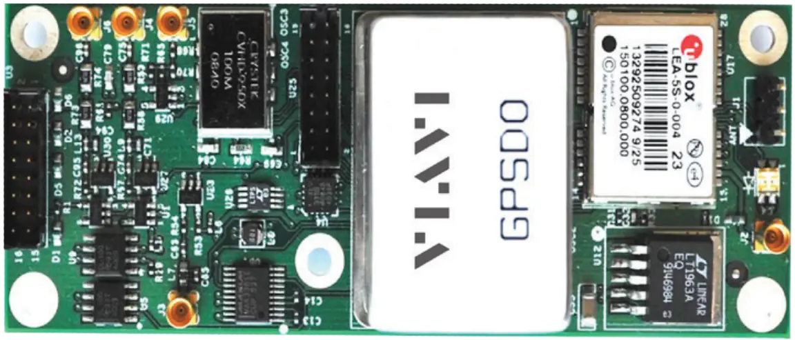
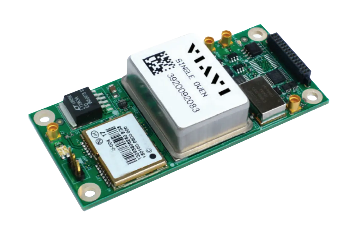
The VIAVI ULN-2550 is a very small GPS Disciplined Oscillator (GPSDO) that serves as a time, frequency and position reference. It is designed for up-conversion applications that need 10 MHz, 25 MHz, 50 MHz and/or 100 MHz sources. The 10 MHz and 100 MHz outputs are always available. The 25 MHz output can be changed to a 50 MHz output with stuffing options.
The module is built around a high-end SC-cut Double Oven Crystal Oscillator (DOCXO) and a 50-channel GPS receiver with -160 dBm tracking sensitivity. It provides four 25/50 MHz LVDS outputs, one 100 MHz CMOS output, one 10 MHz CMOS output and 1 PPS outputs. A WAAS/EGNOS/MSAS-capable GPS receiver disciplines the oscillator under the control of a 32-bit processor. A hold-over mode compensates for aging and temperature.
Apart from the GPS antenna connection, all I/O and power input share one connector. That connector can be a board-to-board interface or a cable harness, which simplifies system integration and supports stringent military requirements.
All outputs are frequency- and phase-synchronized to UTC through GPS, giving Better-Than-Cesium™ long-term performance. The unit is controlled over RS-232 with standard SCPI commands, and settings are stored in non-volatile memory. It is compatible with the GPSCon Windows graphing and SNTP server software. Typical uses are ultra-low-phase-noise up-conversion systems in radar and satellite communication equipment.
Key Features
- 10 MHz, 25 MHz/50 MHz, and 100 MHz outputs with 4x LVDS
- Typical Allan Deviations of <5E-11 with GPS lock for measurement intervals from 1 to 1000 s
- Phase noise of <125 dBc at >10 Hz offsets is standard
- Power consumption of <4 W with DOCXO at 25°C
- High-end WAAS/EGNOS/MSAS GPS receiver drives an ultra-stable OCXO frequency reference under the control of a 32-bit processor
- High-end SC-cut Double Oven Crystal Oscillator
- 50-channel GPS receiver with -160 dBm tracking capability
- Hold-over mode with aging and temperature compensation
- Alarm outputs
- RS-232 control using standard SCPI commands
- Settings automatically stored in non-volatile memory
- Sine Wave, CMOS, and LVDS outputs
- All I/O and power input on a single connector (board-to-board or cable harness), except the GPS antenna
- Outputs frequency- and phase-synchronized to UTC via GPS
- GPSCon Windows graphing and SNTP server software compatible
Specifications
| 1 PPS Accuracy |
±30 ns to UTC RMS (1-Sigma)
GPS Locked
|
|---|---|
| Frequency Accuracy |
Better than ±3E-010
after 1 hour operation with GPS locked
|
| Holdover Stability |
<±7 µs over 24-Hour Period
@+25°C (No Motion, after 5 days with GPS)
|
| ADEV |
1 s to 1000 s: <5 E-11
with GPS lock typical
|
| Warm Up Time/Stabilization Time |
<10 min
at +25°C to 1E-09 Accuracy Typical
|
| Supply Voltage (Vdd) |
11.0 V to 16.0 V DC
Nominal
|
| Power Consumption |
<4 W
at +25°C with DOCXO
|
| Environmental Conformance | MIL-STD-202, Method 204, Condition I-A |
| 1 PPS Outputs (OCXO Flywheel Generated) |
Two outputs: 5 V CMOS and LVDS
Web page lists a 1 PPS LVDS output; datasheet lists both CMOS and LVDS
|
|---|---|
| 10/25/100 MHz Outputs (6x total, 4x @25/50 MHz, 10 MHz, 100 MHz) | 4x LVDS 25/50 MHz, 1x CMOS 100 MHz, 1x CMOS 10 MHz |
| RS-232 Control |
TTL Level, Full control via SCPI-99 Control Commands, NMEA 0183
TTL Level, RS-232 levels optional
|
| TTL Alarm Output | GPS Unlock and Hardware Failure indicator |
| GPS Frequency | L1, C/A 1574 MHz |
|---|---|
| GPS Antenna | Passive or Active, 5 V |
| GPS Receiver | 50 Channels, Mobile, GPS, WAAS, EGNOS, MSAS supported, Galileo ready |
| Sensitivity, Acquisition | -144 dBm |
| Sensitivity, Tracking | -160 dBm |
| GPS TTFF, Cold Start | <45 sec |
| GPS TTFF, Warm Start | 1 sec |
| GPS TTFF, Hot Start | 1 sec |
| Frequency Output | 10 MHz, 25/50 MHz, and 100 MHz outputs |
|---|---|
| 10/100 MHz Retrace without GPS |
±2E-08
After 1 Hour
|
| Frequency Stability |
±2.5E-010 over temperature
low-g option: ±3E-010 per g per axis
|
| Output Amplitude, 10 MHz | CMOS 5V |
| Output Amplitude, 25/50 MHz | LVDS |
| Output Amplitude, 100 MHz | CMOS 3.3V |
| Warm Up Time |
<12 min
Oscillator specification; module warm-up/stabilization time is listed as <10 min to 1E-09
|
| Designed Lifetime | >10 years |
| 1 Hz offset, 25 MHz Out | -88 dBc/Hz |
|---|---|
| 1 Hz offset, 10 MHz Out | -100 dBc/Hz |
| 10 Hz offset, 25 MHz Out | -109 dBc/Hz |
| 10 Hz offset, 10 MHz Out | -125 dBc/Hz |
| 100 Hz offset, 25 MHz Out | -125 dBc/Hz |
| 100 Hz offset, 10 MHz Out | -142 dBc/Hz |
| 1 kHz offset, 25 MHz Out | -145 dBc/Hz |
| 1 kHz offset, 10 MHz Out | -152 dBc/Hz |
| 10 kHz offset, 25 MHz Out | -155 dBc/Hz |
| 10 kHz offset, 10 MHz Out | -155 dBc/Hz |
| 100 kHz offset, 25 MHz Out | -160 dBc/Hz |
| 100 kHz offset, 10 MHz Out | -155 dBc/Hz |
| Operating Temperature | -25°C to +75°C |
|---|---|
| Storage Temperature | -45°C to +85°C |
Specifications are taken from the manufacturer's documentation. See the datasheet for complete and current values.
Applications
- Ultra low-phase-noise up-conversion systems
- Radar equipment
- Satellite communication equipment
- Defense
- 5G communications
- SATCOM
- Transportation
- Data center
- Energy
- Financial
- Critical infrastructure
Options & Accessories
| Option | Description |
|---|---|
| 1002501-G2 | ULN 2550 25MHz SOCXO GPSDO OEM Board - non-RoHS |
| 22174855 | ULN 2550 25MHz SOCXO GPSDO OEM Board - RoHS |
| 22174860 | ULN 2550-G2 50MHz SOCXO - RoHS |
| 22174861 | ULN 2550-G2 50MHz SOCXO RS232 - RoHS |
| 1001026-ST-G2 | ULN-2550 25MHz DOCXO Ruggedized EC GPSDO OEM Board Low G - non-RoHS |
| 22174845 | ULN-2550 25MHz DOCXO Ruggedized CC GPSDO OEM Board Low G - RoHS |