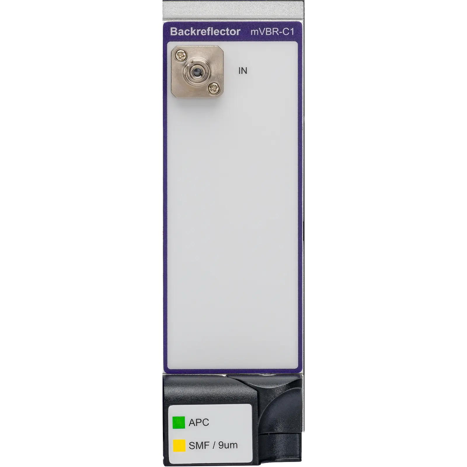
VIAVI MAP Variable Back Reflector Module mVBR-C1 Optical Back Reflector Cassette
MAP Series cassette that applies precise, adjustable levels of return loss to transmitters, with 0.005 dB resolution.
- Wavelength Range
- 1260 to 1650 nm
- Wavelength Range
- 750 to 1350 nm
- Maximum Back Reflection Level
- -5.0 dB
- Minimum Back Reflection Level
- -60 dB
Overview
The VIAVI MAP Series Variable Back Reflector (mVBR-C1) is a metrology-grade optical back reflector cassette for the Multiple Application Platform (MAP). It provides precise levels of return loss to transmitters, enabling measurement of system sensitivity and system degradation as a function of back reflection.
In transmission systems, power fluctuations caused by back reflection distort the signal and increase the bit error rate. Used together with a transmitter/receiver pair and characterization equipment, the mVBR establishes the magnitude of reflections that significantly degrade transmission performance and helps characterize the problems they cause. A typical setup uses an external coupler that splits light from the source under test, sending part to the mVBR and the rest to the test system.
The module uses the VIAVI linear attenuator prism and a high-reflectivity mirror to control the return loss level. An offset setting compensates for losses at connectors and in any additional components between the source and the mVBR. The cassette is available with single-mode or multimode fiber and with an optional coupler for monitoring.
Platform and control
The mVBR belongs to the LightDirect module family of the MAP platform and is compatible with current MAP-300 and MAP-200 chassis through SCPI commands, with a graphical user interface offered on the MAP-300. When installed in a MAP mainframe it can be automated through LXI-compliant interfaces and IVI drivers, and combined with other MAP-Series modules for IEEE standard testing.
Key Features
- Single-mode and multimode variants
- 0.005 dB back reflection resolution
- Operation at 850/1310 or 1310/1550 nm
- Automation via MAP mainframe LXI-compliant interfaces and IVI drivers
- Can be combined with other MAP-Series modules for IEEE standard testing
- VIAVI linear attenuator prism and high-reflectivity mirror control the RL level
- Offset setting to compensate for connector and component losses
- Optional coupler for monitoring
- Compatible with MAP-300 and MAP-200 chassis through SCPI commands
Specifications
|
Wavelength Range
Single-Mode
|
1260 to 1650 nm |
|---|---|
|
Wavelength Range
Multimode
|
750 to 1350 nm |
| Maximum Back Reflection Level | -5.0 dB |
|
Minimum Back Reflection Level
Single-Mode
|
-60 dB |
|
Minimum Back Reflection Level
Multimode
|
-35 dB |
| Back Reflection Resolution |
0.005
The product page states 0.005 dB resolution
|
| Repeatability |
± 0.02 dB
At 23 ±5°C; source line width > 500 MHz; maximum measured difference between consecutive 25 dB back reflection settings, separated by a random setting, observed for 100 measurements
|
|
Absolute Back Reflection Accuracy
Single-Mode
|
±0.3 dB
At 1310 nm ±15 nm and 1550 nm ±15 nm; at 23 ±5°C; source line width > 500 MHz
|
|
Absolute Back Reflection Accuracy
Multimode
|
±0.6 dB
At 850 nm ±15 nm and 1300 ±15 nm; at 23 ±5°C; source line width > 500 MHz
|
|
Relative Back Reflection Setting Accuracy
Single-Mode
|
±0.05 dB
At 1310 nm ±15 nm and 1550 nm ±15 nm; at 23 ±5°C; source line width > 500 MHz
|
|
Relative Back Reflection Setting Accuracy
Multimode
|
±0.35 dB
At 850 nm ±15 nm and 1300 ±15 nm; at 23 ±5°C; source line width > 500 MHz
|
|
Polarization Dependent Back Reflection
Single-Mode
|
< 0.15 dB
At 1310 nm ±15 nm and 1550 nm ±15 nm; N/A for multimode
|
| Maximum Optical Input Power | 200 mW |
|
Fiber Type
Single-Mode
|
9/125 µm |
|---|---|
|
Fiber Type
Multimode
|
50/125 µm |
|
Connector Type
Single-Mode
|
FC/APC |
|
Connector Type
Multimode
|
FC/PC |
| Warm-up time | 30 minutes |
|---|---|
| Calibration Period | 1 year |
| Safety |
Complies with CE, CSA/UL/IEC61010-1, plus LXI class C requirements
When installed in a MAP chassis
|
| Operating Humidity | 15 to 80% RH, 0 to 40°C noncondensing |
|---|---|
| Operating Temperature | 0 to 50°C |
| Storage Temperature | -30 to 60°C |
| Dimensions (W x H x D) | 4.1 x 13.3 x 37.0 cm (1.6 x 5.22 x 14.58 in) |
|---|---|
| Weight | 1.1 kg (2.42 lbs) |
Specifications are taken from the manufacturer's documentation. See the datasheet for complete and current values.
Applications
- Transmitter/receiver development and testing
- Reflection testing for connectors
- Quality assurance acceptance testing
- Laser development and production
- Validation of RL measurement equipment
- R&D compliance testing
- OTDR testing
Options & Accessories
| Option | Description |
|---|---|
| MVBR-C1SS0-M100-MFA | Single VBR Single Mode Fiber FC/APC no tap option |
| MVBR-C1SS0-M101-MFP | Single VBR Multi-Mode Fiber 50µm FC/PC no tap option |
| CleanBlastPRO | CleanBlast fiber end-face cleaning system — Optional inspection and cleaning tool for removing dirt and debris from connectors in most common applications. |
| FiberChek Probe | FiberChek probe microscope — Optional one-button, fully autonomous handheld fiber inspection solution. |
| P5000i | P5000i fiber microscope — Optional automated fiber inspection and analysis probe with PASS/FAIL capability for PCs, laptops, mobile devices and VIAVI test solutions. |
| AC500 | FC/PC-FC/PC Universal Connector Adapter — Replacement part (mating sleeve) |
| AC501 | FC/PC-SC/PC Universal Connector Adapter — Replacement part (mating sleeve) |
| AC502 | FC/APC-FC/APC Universal Connector Adapter — Replacement part (mating sleeve) |
| AC503 | FC/APC-SC/APC Universal Connector Adapter — Replacement part (mating sleeve) |