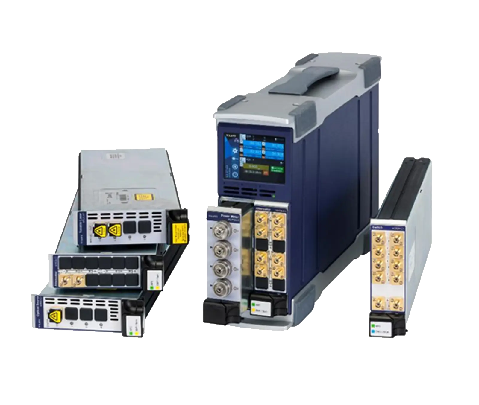
VIAVI PCT-rm (mOLM-C1) Single Fiber Insertion Loss and Return Loss Test System
MAP-220C based benchtop system for concurrent insertion loss and return loss testing of single fiber connectors in the lab and in manufacturing.
- Wavelength combinations
- 1310/1550 nm; 1310/1490/1550/1625 nm
- Wavelength combinations
- 850/1300 nm
- Wavelength accuracy
- ± 10 nm
- Multimode launch conditions
- As per IEC 61280-4-1
Overview
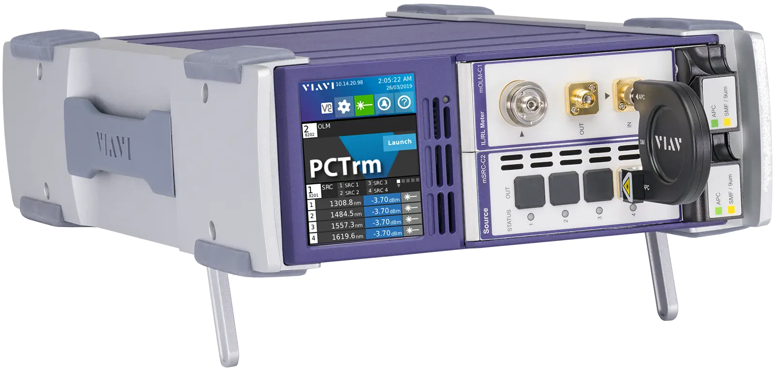
The VIAVI PCT-rm is an insertion loss (IL) and return loss (RL) test solution based on the MAP-220 platform, aimed at single fiber connector applications in the lab and in manufacturing. It is part of the MAP-Series Passive Connector Test (PCT) solution family and the extended MAP LightTest family of application-specific solutions for passive components and optical connectors.
Building on the heritage of the JDSU RM and RX meters, the PCT-rm uses the optical continuous wave reflection (OCWR) test method. A patented real-time measurement engine makes measurement performance and speed independent of the number of measured wavelengths; all four wavelengths are reported in less than 0.5 s, with IL and RL measured concurrently. A range of power meter connector adapters allows the unit to be configured for different connectivity applications.
The system combines the mOLM-C1 measurement module with an mSRC-C2 source module in a two-slot MAP-220C benchtop chassis, which also gives access to the broader MAP series capabilities. Multimode (EF compliant), single-mode and tunable sources are supported.
Measurement modes
Instrument Mode is always available from the 3.5-inch touch screen or through remote VNC, with one-touch referencing for IL and RL and user-controllable resolution and averaging time. The display can show absolute power, insertion loss, or insertion loss and return loss, and an external light source such as a tunable laser can be configured. Device Aware Mode provides an integrated workflow automation environment: DUT definition files and serial numbers can be pre-loaded, and results can be uploaded automatically to a shared network directory.
PCT Control Center
PCT Control Center is a companion PC application delivered standard with the PCT-rm. It is used to create and manage DUT definition files, report templates and serial number batches, and to view, filter and print test results using HTML templates. Files can be shared over the network or transferred on USB storage, and the application is also compatible with the PCT-lite system based on the mORL-A1 measurement engine.
Key Features
- Real-time, high-repeatability system for insertion loss and return loss
- OCWR (optical continuous wave reflection) test method
- All four wavelengths measured in less than 0.5 s, IL and RL measured concurrently
- Combines the mOLM-C1 measurement module with an mSRC-C2 source module in a MAP-220C chassis
- Modular design supporting multimode (EF compliant), single-mode and tunable sources
- Two-slot benchtop chassis with access to the broader MAP series system capabilities
- Large 3.5-inch multi-language color touch screen
- LXI compliant LAN connectivity
- SCPI based remote commands over Ethernet or an optional GPIB interface
- Instrument Mode and Device Aware Mode for production workflow automation
- PCT Control Center PC application for data management and report printing
- PC based asset management tool to collect and centrally store data on remote network drives
- Multiple USB ports supporting a USB foot pedal
Specifications
|
Wavelength combinations
SMF
|
1310/1550 nm; 1310/1490/1550/1625 nm
Peak wavelength defined per IEC 61280-1-3 2010 clause 3.1.3
|
|---|---|
|
Wavelength combinations
MMF (50 μm)
|
850/1300 nm
Peak wavelength defined per IEC 61280-1-3 2010 clause 3.1.3
|
| Wavelength accuracy | ± 10 nm |
|
Multimode launch conditions
MMF (50 μm)
|
As per IEC 61280-4-1 |
| Wavelength range | 800-1650 nm |
|---|---|
| Fiber type | SMF and MMF with NA < 0.27 |
| Dynamic range | +6 dBm to -70 dBm |
| Display resolution | 0.001 dB |
| Linearity | ± 0.015 dB ± 5 pW |
| Uncertainty at reference condition |
± 3.0%
Reference condition: input fiber SMF-28, T = 23 ±5°C, spectral width of source < 6nm, -20 dBm input power
|
| Additional uncertainty due to polarization | ± 0.015 dB |
| Noise | ± 3 pW |
| Detector return loss (APC connector) | > 65 dB |
| Max measurement speed (4 lambda) |
All wavelengths measured in 0.5 s
Measured concurrently with return loss; tested in wavelength cycling mode using specified mSRC-C2, within 5 min of an IL reference and observed over 15 min, ignores any PDL contribution from DUT
|
|---|---|
| Display resolution | 0.001 dB |
| Display range | 0 to -60 dB |
|
Accuracy, 0 to -40 dB
SMF, MMF (50 μm)
|
± 0.04 dB
> -8 dBm reference power
|
|
Accuracy, -40 to -50 dB
SMF
|
± 0.05 dB
> -8 dBm reference power; NA for MMF
|
|
Repeatability, 0 to -40 dB
SMF
|
± 0.002
> -10 dBm reference power
|
|
Repeatability, 0 to -40 dB
MMF (50 μm)
|
± 0.005
> -10 dBm reference power
|
|
Repeatability, -40 to -50 dB
SMF
|
± 0.005
> -10 dBm reference power; NA for MMF
|
| Max measurement speed (4 lambda) |
All wavelengths measured in 0.5 s
Measured concurrently with insertion loss
|
|---|---|
|
Display dynamic range
SMF
|
10 to 80 dB |
|
Display dynamic range
MMF (50 μm)
|
10 to 50 dB |
| Display resolution | 0.01 dB |
|
Accuracy, 10 dB to 50 dB
SMF, MMF (50 μm)
|
± 0.3 dB
> -8 dBm reference power
|
|
Accuracy, 50 dB to 65 dB
SMF
|
± 0.4 dB
> -8 dBm reference power; NA for MMF
|
|
Accuracy, 65 dB to -70 dB
SMF
|
± 1.0 dB
> -8 dBm reference power; range printed as '65 dB to -70 dB' in the datasheet; NA for MMF
|
|
Accuracy, 70 dB to 75 dB
SMF
|
± 2.0 dB
> -8 dBm reference power; NA for MMF
|
|
Repeatability, 10 dB to 50 dB
SMF
|
± 0.02 dB
> -10 dBm reference power
|
|
Repeatability, 10 dB to 50 dB
MMF (50 μm)
|
± 0.3 dB
> -10 dBm reference power
|
|
Repeatability, 50 dB to 65 dB
SMF
|
± 0.4 dB
> -10 dBm reference power; NA for MMF
|
|
Repeatability, 65 dB to 70 dB
SMF
|
± 1.0 dB
> -10 dBm reference power; NA for MMF
|
|
Repeatability, 70 dB to 75 dB
SMF
|
± 2.0 dB
> -10 dBm reference power; NA for MMF
|
| Measurement conditions |
All optical measurements performed 60 minutes after power on in a controlled environment of 23±2°C
All uncertainties are 2σ values unless otherwise stated; mSRC-C2 and mOLM-C1 connected with the rigid jumper supplied with the system
|
| CPU | ARM AM335x |
|---|---|
| Operating system | Linux OS |
| Memory | 4GB user flash memory |
| Controller serviceability | Field replaceable (co-packaged with Power supply) |
| Display |
3.5-inch color screen, 320 x 240 resolution
Capacitive touchscreen
|
| Remote interface | Ethernet 10/100/1000Base-T; GPIB (optional) |
|---|---|
| USB device support | Mouse, keyboard, memory stick, foot pedal |
| Power supply |
100 to 240 V AC, 50/60 Hz
Auto-switching; field replaceable (co-packaged with controller)
|
|---|---|
| Power consumption | 160 VA |
| Local laser interlock | Software password controlled |
| Safety compliance | Complies to CE, CSA/UL/IEC61010-1, LXI Class C requirements, meets the requirements of IEC 60825-1 (2014) Class 1M and complies with 21 CFR 1040.1 except deviations per Laser Notice No. 50, July 2001 |
| Operating temperature |
10 to 40°C
The MAP-220C chassis datasheet rates the chassis alone at 0 to 50°C; the system datasheet value is used here
|
|---|---|
| Storage temperature | –30 to 60°C |
| Relative humidity | 5 to 85% noncondensing |
| Dimensions (W x H x D) | 220 x 88.2 x 387 mm (8.66 x 3.47 x 15.24 in) |
|---|---|
| Weight | 8 kg (17.6 lbs) |
|
MAP-RM-C13500FB-M100-MFA
MAP-RM-C13500FB-M100-MFA
|
1310/1550 nm Basic FP laser, FC/APC
Single mode fiber, dual wavelength
|
|---|---|
|
MAP-RM-C13500FP-M100-MFA
MAP-RM-C13500FP-M100-MFA
|
1310/1550 nm FP laser with Temperature Control, FC/APC
Single mode fiber, dual wavelength
|
|
MAP-RM-C13456FP-M100-MFA
MAP-RM-C13456FP-M100-MFA
|
1310/1490/1550/1625 nm FP laser with Temperature Control, FC/APC
Single mode fiber
|
|
MAP-RM-C11308LP-M101-MFA
MAP-RM-C11308LP-M101-MFA
|
850/1300 nm LED 50um MMF EF compliant, FC/APC
50um multimode fiber solution
|
Specifications are taken from the manufacturer's documentation. See the datasheet for complete and current values.
Applications
- Single fiber connector manufacturing
- Qualification testing of connectors
- Testing of simple broadband passive components
Included
- MAP-220C mainframe
- mOLM-C1 measurement module
- mSRC-C2 source module
- Interconnection jumper to connect mSRC and mOLM modules
- One FC style power meter adaptor
- PCT Control Center PC application
Options & Accessories
| Option | Description |
|---|---|
| MAP-RM-C13500FB-M100-MFA | PCT-rm system, SMF, 1310/1550 nm Basic FP laser, FC/APC — Preconfigured MAP-220 IL/RL meter variant |
| MAP-RM-C13500FP-M100-MFA | PCT-rm system, SMF, 1310/1550 nm FP laser with Temperature Control, FC/APC — Preconfigured MAP-220 IL/RL meter variant |
| MAP-RM-C13456FP-M100-MFA | PCT-rm system, SMF, 1310/1490/1550/1625 nm FP laser with Temperature Control, FC/APC — Preconfigured MAP-220 IL/RL meter variant |
| MAP-RM-C11308LP-M101-MFA | PCT-rm system, 850/1300 nm LED 50um MMF EF compliant, FC/APC — Preconfigured MAP-220 IL/RL meter variant |
| MAP-200CGPIB-A | GPIB Interface Option |
| MAP-200C01 | Rack-mount conversion kit |
| MAP-200C02 | Benchtop conversion kit |
| MAP-200CLD-A | Replacement LightDirect Controller |
| MAP-200A020 | Hardened inter-connection jumper, SMF, FC/APC |
| MAP-200A021 | Hardened inter-connection jumper, OM3, FC/PC |
| AC500 | Replacement bulkhead adapter FC/PC |
| AC502 | Replacement bulkhead adapter FC/APC |