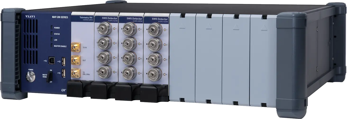
VIAVI MAP Swept Wavelength System mSWS-A2 for DWDM Component and ROADM Test
MAP-300 based swept wavelength test system measuring IL, PDL, RL and directivity of DWDM devices, ROADMs and circuit packs versus wavelength.
- Range
- 1520.086 to 1630 nm
- Accuracy
- ±2 pm absolute
- Resolution
- User selectable at 3, 1.5, 0.75, or 0.4 pm
Overview
The VIAVI MAP Swept Wavelength System (mSWS-A2) is a test system for measuring insertion loss (IL), polarization dependent loss (PDL), return loss (RL) and directivity of DWDM devices as a function of wavelength. It is used in both research and development and production environments for components and modules such as colorless, directionless, contentionless (CDC) ROADMs, high-port-count wavelength switches, tunable filters and circuit packs.
The system consists of a tunable laser source, a source optics module (SOM), a control module, a receiver chassis, one or more detector modules and application software. It combines the SWS2000 tunable laser and SOM with a measurement receiver based on the VIAVI MAP-300 photonics test platform. The distributed architecture supports up to eight separately controlled measurement stations from one source laser, and installed SWS2000 systems can be upgraded by adding mSWS-A2 based measurement stations.
Measurement
A 4-state polarization controller in the SOM measures four polarization states (0°, 90°, –45° and circular) and uses Mueller matrix analysis to determine PDL and average loss at all scanned wavelengths. Return loss is measured with the optional ORL utility cassette. The wavelength resolution is user selectable between 0.4 and 3 pm.
Software
The application software calculates loss at peak, center wavelength, loss at center wavelength, bandwidth at a given threshold, crosstalk and flatness relative to the measured peak, the ITU grid or a user-defined grid. A set of DLLs gives access to all SWS functionality for custom applications in Visual Basic, C, C++ or LabView. Integration into the MAP-300 platform allows automation with additional switches, laser sources and connector inspection tools.
Key Features
- Scalable architecture supporting up to 8 measurement stations from one TLS/SOM transmitter station
- ±0.002 nm absolute wavelength accuracy over 1520 to 1630 nm
- Up to 256 detector channels per station
- User-selectable wavelength resolution from 0.4 to 3 pm
- Sweep rates up to 100 nm/s with full performance specifications
- Dynamic range of >70 dB
- 4-state polarization controller with Mueller matrix PDL analysis
- Analysis relative to measured peak, ITU grid or user-defined grid
- DLLs for custom applications in Visual Basic, C, C++ or LabView
- Upgrade path for installed SWS2000 systems
Specifications
| Range | 1520.086 to 1630 nm |
|---|---|
| Accuracy |
±2 pm absolute
Web page states ± 0.002 nm absolute wavelength accuracy
|
| Resolution | User selectable at 3, 1.5, 0.75, or 0.4 pm |
| SOM sweep rates |
10, 20, 40, and 100 nm/s
All channels are measured in parallel. Web page states high speed scanning up to 40 nm/s; datasheet lists up to 100 nm/s
|
|---|---|
| C band sweep period at 10 nm/s |
8 s
In continuous scanning mode with delay set to zero and direct Ethernet connection; high-channel-count systems will require several seconds of delay
|
| C band sweep period at 20 nm/s |
5.5 s
In continuous scanning mode with delay set to zero and direct Ethernet connection
|
| C band sweep period at 40 nm/s |
4 s
In continuous scanning mode with delay set to zero and direct Ethernet connection
|
| C band sweep period at 100 nm/s |
3 s
In continuous scanning mode with delay set to zero and direct Ethernet connection
|
| C+L band sweep period at 10 nm/s |
15 s
In continuous scanning mode with delay set to zero and direct Ethernet connection
|
| C+L band sweep period at 20 nm/s |
9 s
In continuous scanning mode with delay set to zero and direct Ethernet connection
|
| C+L band sweep period at 40 nm/s |
6 s
In continuous scanning mode with delay set to zero and direct Ethernet connection
|
| C+L band sweep period at 100 nm/s |
4 s
In continuous scanning mode with delay set to zero and direct Ethernet connection
|
| Measurement range, stand-alone station |
70 dB
For > 10 dBm to DUT
|
|---|---|
| Measurement range, distributed station |
60 dB
For > 10 dBm to DUT
|
| Noise at 10 nm/s, 0 to –20 dB |
< ±0.005 dB
Noise value is 3 X standard deviation
|
| Noise at 10 nm/s, –20 to –40 dB |
< ±0.02 dB
Noise value is 3 X standard deviation
|
| Noise at 10 nm/s, –40 to –50 dB |
< ±0.05 dB
Noise value is 3 X standard deviation
|
| Noise at 10 nm/s, –50 to –60 dB |
< ±0.2 dB
Noise value is 3 X standard deviation
|
| Base uncertainty |
±0.03 dB
Total IL uncertainty before noise or slope error, assuming SOM to mSWS-A2RX receiver fiber static, FC/PC connector to mSWS-A2DM detector, and temperature within ±1°C
|
| Resolution | 0.001 dB |
| Maximum slope tracking |
>0.4 dB/pm
At 10 nm/s, 0 to –60 dB IL
|
| Measurement range |
60 dB
Requires ORL utility cassette, which is used in conjunction with mSWS-A2DM and mSWS-A2RX cassettes
|
|---|---|
| Noise at 10 nm/s, 0 to –20 dB |
< ±0.02 dB
Noise value is 3 X standard deviation
|
| Noise at 10 nm/s, –20 to –40 dB |
< ±0.06 dB
Noise value is 3 X standard deviation
|
| Noise at 10 nm/s, –40 to –50 dB |
< ±0.2 dB
Noise value is 3 X standard deviation
|
| Noise at 10 nm/s, –50 to –60 dB |
< ±0.5 dB
Noise value is 3 X standard deviation
|
| Measurement range |
50 dB
At –10 dBm to DUT and a sweep rate of 10 nm/s; measurement range reduced at higher speeds
|
|---|---|
| Noise at 10 nm/s, 0 to –20 dB |
< ±0.01 dB
Noise value is 3 X standard deviation
|
| Noise at 10 nm/s, –20 to –40 dB |
< ±0.04 dB
Noise value is 3 X standard deviation
|
| Noise at 10 nm/s, –40 to –50 dB |
< ±0.1 dB
Noise value is 3 X standard deviation
|
| Resolution | 0.001 dB |
| Dynamic range | >70 dB |
|---|---|
| Measurement stations per source laser | up to eight |
| Detector channels per station | Up to 256 |
| Polarization states |
0°, 90°, –45°, and circular polarization
4-state polarization controller located within the SOM; Mueller matrix analysis
|
| Compliance | CE requirements as well as UL3101.1 and CAN/CSA - C22.2 No. 1010.1 |
|---|---|
|
Source Optics Module laser class
SWS20010
|
Class 1
Classified per IEC standard 60825-1(2002); complies with 21CFR1040.10, except for deviations per Laser Notice No. 50, July 2001
|
|
Tunable Laser Source laser class
SWS17101
|
Class 3B
Classified per IEC standard 60825-1(2002); web page also lists SWS18101
|
Specifications are taken from the manufacturer's documentation. See the datasheet for complete and current values.
Applications
- Optical component and module characterization in manufacturing, development and research
- ROADMs
- Wavelength-selective switches
- Wavelength blockers
- Optical circuit packs
- DWDM and CWDM devices
- Tunable filters
- Couplers and splitters
- Optical switches and attenuators
- Fiber Bragg gratings (FBGs)
- Interleavers
- Dichroic filters
- MEMS and waveguide devices
Options & Accessories
| Option | Description |
|---|---|
| mSWS-A2SLS | C+L band tunable laser — mSWS core system |
| mSWS-A2S0M | Dual-output integrated source optic module (SOM) — mSWS core system |
| mSWS-A2TX | Four-output telemetry transmitter expansion module (SOM) — mSWS core system |
| MAP-380 | MAP-300 8-slot mainframe — mSWS core system; refer to MAP-300 data sheet for available mainframe options |
| mSWS-A2DM | mSWS quad detector module — mSWS core system |
| mSWS-A2RX | mSWS telemetry receiver — mSWS core system |
| mUTL-A1000 | ORL utility cassette — With option MUTL-A150LR |
| mSWS-PMJ | PM fiber jumper for mSWS — mSWS core system |
| AC900 | Detector cap |
| AC901 | FC detector adapter |
| AC102 | ST detector adapter |
| AC903 | SC detector adapter |
| AC918 | LC detector adapter |
| AC920 | Bare fiber adapter holder |
| AC921 | Bare fiber adapter — Includes one AC920 |