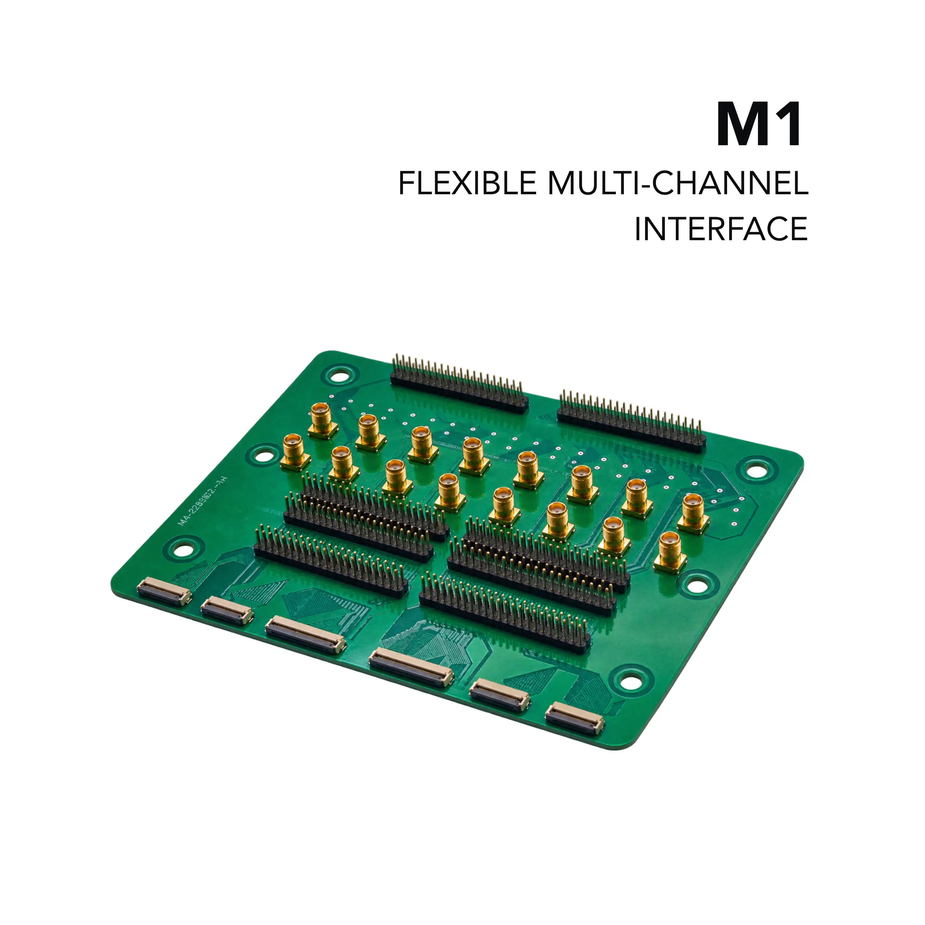
Multiconnector M1 40-Channel Passive Interconnect Board
40-channel passive multi-connector board with FFC, 2.54 mm pin-header and SMA interfaces for connecting XPOW/XDAC systems to a DUT.
- Dimensions (L × W × H)
- 12 × 16 × 12 mm
- Channels
- 40
- Board type
- Passive interconnect / reconfiguration PCB
Overview
The Nicslab Multiconnector M1 is a passive 40-channel interconnect board (type 1 / M1) that sits between the main XPOW/XDAC system and a device under test (DUT). It breaks out the 40 channels to FFC connectors, 2.54 mm pin headers and SMA connectors, so the same board can be wired to suit different DUT connector types without modifying the main system.
Connection points
The board is organised into lettered callouts A–R. Points A–H and M connect to the DUT, points I–L are reconfiguration pins, points N and O are ground checkpoints, point P is the per-channel output checkpoint, and points Q and R connect to the main system. Points Q and R are pre-wired at the factory, with GND and the corresponding channel outputs already mapped.
Wiring and reconfiguration
The Y-side group (callouts C, G and I) and the X-side group (callouts D, H and J) are each connected together, so a given Y or X pin is available on the FFC connector and on both associated pin headers. Points K and L correspond directly to points Q and R, with the top row as GND and the bottom row (C1–C40) as channel outputs. In the factory default configuration, with a cable attached across points I, J, K and L, Y1–Y20 and X1–X20 are GND, Y21–Y40 carry CH1–20 outputs and X21–X40 carry CH21–40 outputs. Jumper cables between points I/J and K/L allow custom GND and signal layouts, for example alternating GND and signal pins on an FFC.
Usage
A DUT with SMA inputs can be connected directly to any of the SMA connectors (CH1–CH16), which are already wired through to the main system; the matching channel is then selected in the control GUI. A DUT with a 2.54 mm pin-header input can be wired from point G or H in the factory default configuration. Ground and per-channel checkpoints allow verification with a multimeter without disconnecting cabling.
Key Features
- 40 channels broken out across FFC connectors, 2.54 mm pin headers, and SMA connectors
- SMA connectors for CH1–CH16 at point M
- Six FFC connectors (points A–F, 20–50 pin) carrying the X and Y channel groups
- Dedicated reconfiguration pin headers (points I–L) to remap channel/GND assignments
- Ground checkpoints (2 pins, points N/O) for multimeter verification
- Per-channel output checkpoints (point P, 1–40) for verification without disconnecting cabling
- Direct pass-through connectors (points Q/R) to the main XPOW/XDAC system, factory pre-wired
- Compact, passive PCB with no external power required beyond what passes through from the main system
- Supports multiple simultaneous DUT connection types (FFC, pin header, and/or SMA) from a single board
Specifications
| Dimensions (L × W × H) | 12 × 16 × 12 mm |
|---|---|
| Channels | 40 |
| Board type | Passive interconnect / reconfiguration PCB |
| A |
FFC-6 24 pin (Y21–Y40, Y1-Y4)
Connects to DUT
|
|---|---|
| B |
FFC-5 20 pin (Y21–Y40)
Connects to DUT
|
| C |
FFC-4 50 pin (Y21, Y22, Y23–Y40, Y1–Y8, Y9, Y10)
Connects to DUT; connected to points G and I
|
| D |
FFC-3 50 pin (X21, X22, X23–X40, X1–X8, X9, X10)
Connects to DUT; connected to points H and J
|
| E |
FFC-2 20 pin (X21–X40)
Connects to DUT
|
| F |
FFC-1 24 pin (X21–X40, X1-X4)
Connects to DUT
|
| G |
2x20-1 pin header 2.54 mm (Y1–Y40)
Connects to DUT
|
| H |
2x20-2 pin header 2.54 mm (X1–X40)
Connects to DUT
|
| I |
2x20-3 pin header 2.54 mm (Y1–Y40)
Reconfiguration pins
|
| J |
2x20-4 pin header 2.54 mm (X1–X40)
Reconfiguration pins
|
| K |
2x20-5 pin header 2.54 mm ((C21–C40) + GND)
Reconfiguration pins; top row GND, bottom row channel outputs
|
| L |
2x20-6 pin header 2.54 mm ((C1–C20) + GND)
Reconfiguration pins; top row GND, bottom row channel outputs
|
| M |
SMA connectors (CH1–CH16)
Connects to DUT; wired through to the main system via points Q/R
|
| N | GND check point 1 pin (41) |
| O | GND check point 2 pin (42) |
| P | Channel 1–40 output check point pin (1-40) |
| Q |
21-40 CH in 2x20-7 pin header 2.54 mm (21–40)
Connects to main system; factory pre-wired
|
| R |
1–20 CH in pin header 2.54 mm (1–20)
Connects to main system; factory pre-wired
|
| Output connector | FFC (points A–F), 2.54 mm pin header (points G–J), or SMA (point M) — multiple types available simultaneously |
|---|---|
| Reconfiguration | Points I–L allow remapping of channel/GND assignment away from factory default |
| Verification | GND checkpoints (N/O) and per-channel checkpoints (P, 1–40) for multimeter probing |
| Factory default mapping |
Y1–Y20 and X1–X20 = GND; Y21–Y40 = CH1–20 outputs; X21–X40 = CH21–40 outputs
With a cable attached across points I, J, K, and L
|
Applications
- Connecting XPOW/XDAC systems to devices under test
- DUTs with SMA inputs
- DUTs with 2.54 mm pin-header inputs
- DUTs with FFC inputs and custom GND/channel layouts
- Multimeter verification of channel outputs