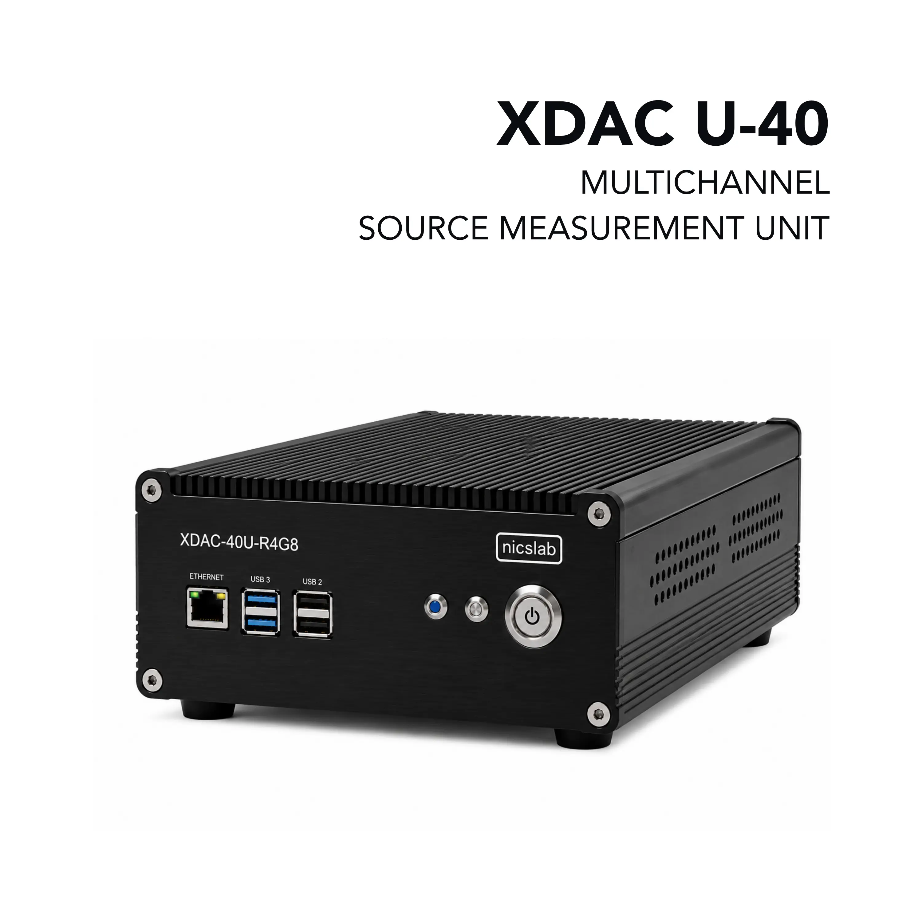
Nicslab XDAC U-40 XDAC-40U-R4G8 40-Channel Unipolar Multichannel Source Measurement Unit
40-channel unipolar source measurement system with 16-bit voltage and current control, 0–34 V / 0–300 mA per channel and Ethernet control.
- Channels / Output Quadrant
- 40 / Unipolar (single-quadrant, source only)
- Operating modes
- Constant Current (CC) 0 to 300 mA per channel; Constant Voltage (CV) unipolar 0 – 5 V, 0 – 10 V, 0 – 20 V, 0 – 34 V
- Measurement Time
- 100 ms
- Max. Output Power
- 10 W per channel
Overview
The Nicslab XDAC U-40 (SKU XDAC-40U-R4G8) is a compact multichannel source measurement system with 40 independently controlled unipolar channels. Each channel supports voltage or current sourcing together with real-time voltage and current measurement, for low-power applications ranging from simple electronic circuits to complex photonic integrated circuits.
The instrument operates in two modes: Constant Current (CC), from 0 to 300 mA per channel, and Constant Voltage (CV), up to 34 V. Voltage and current control use 16-bit resolution, and output ranges can be selected in software without losing resolution. Maximum output power is 10 W per channel.
Software and control
The system is operated from a graphical user interface or through SCPI commands over Ethernet (a USB-to-Ethernet adapter is included), with examples for Python, MATLAB, LabVIEW and C#. The GUI runs on Windows, macOS and Linux.
Basic and Premium tiers
The Basic version works on a fixed 0–34 V / 0–300 mA output range. The Premium upgrade adds software-selectable voltage ranges (0–5 V, 0–10 V, 0–20 V) and current ranges down to 0–3.125 mA, configuration save and upload, CC/CV sequence automation, data recording, per-channel voltage and current limits, threshold and short-circuit protection, adjustable reading speed and the SCPI software library.
Key Features
- 40 independently controlled channels
- Unipolar, single-quadrant sourcing from 0 to 34 V and 0 to 300 mA
- Constant Current (CC, 0–300 mA) and Constant Voltage (CV, 0–34 V) operating modes
- 16-bit voltage control with software-selectable ranges 0–5 V, 0–10 V, 0–20 V and 0–34 V (Premium)
- 16-bit current control with software-selectable ranges from 0–300 mA down to 0–3.125 mA (Premium, firmware 4.1.1.1 and up)
- Real-time voltage and current reading on every channel
- Configurable reading speed through averaging sample count and ADC conversion time
- Maximum output power of 10 W per channel
- Control via GUI or SCPI commands (Python, MATLAB, LabVIEW, C#)
- Ethernet port with USB-to-Ethernet adapter included
- GUI support for Windows, macOS and Linux
- Configuration save and upload as CSV files (Premium)
- CC/CV sequence automation with programmable delay time (Premium)
- Data recording at a selectable interval (Premium)
- Per-channel voltage/current limits, threshold and short-circuit protection (Premium)
- Control of multiple XDAC units from one GUI (optional)
- GPIO for external control and monitoring
- CE and RoHS3 (2015/863) compliant
- 3-year limited warranty
Specifications
| Channels / Output Quadrant | 40 / Unipolar (single-quadrant, source only) |
|---|---|
| Operating modes |
Constant Current (CC) 0 to 300 mA per channel; Constant Voltage (CV) unipolar 0 – 5 V, 0 – 10 V, 0 – 20 V, 0 – 34 V
Voltage sub-ranges require the Premium upgrade
|
| Measurement Time |
100 ms
The reference manual gives 104 ms for a single channel
|
| Max. Output Power | 10 W per channel |
| Calibration period | 2 years |
| Voltage Sourcing Range |
0–5 V / 0–10 V / 0–20 V / 0–40 V (34 V)
Basic version: fixed 0–40 V (34 V) range; sub-ranges are a Premium feature
|
|---|---|
| Voltage Resolution |
0.15 – 0.6 mV (range-dependent)
The reference manual lists 76 μV for the 0–5 V range
|
| Voltage Accuracy | ±0.04 – ±0.25 %FSR (range-dependent) |
| Slew Rate |
4 V/µs
All ranges except 0–5 V
|
| Current Sourcing Range |
0 – 300 mA (unipolar, source only)
Basic version: fixed 0–300 mA range; sub-ranges are a Premium feature (firmware 4.1.1.1 and up)
|
|---|---|
| Current Resolution |
10 µA (range-dependent)
The reference manual lists 4.5 µA control resolution on the 0–300 mA range
|
| Current Accuracy |
±0.4 – ±1.4 %FSR
Total unadjusted error, 300 mA range
|
| Voltage Measurement |
0–34 V range, 1 mV resolution
The reference manual gives real-time voltage reading 16-bits resolution = 1.25 mV
|
|---|---|
| Current Measurement |
0–300 mA range, 10 µA resolution
The reference manual gives real-time current reading 16-bits resolution = 5 μA
|
| Averaging samples |
1, 4, 16, 64, 128, 256, 512, 1024 Samples
Selectable via measurement configuration
|
| V and I ADC conversion time |
50 µS, 84 µS, 150 µS, 280 µS, 540 µS, 1052 µS, 2074 µS, 4120 µS
Selectable via measurement configuration
|
| 0 – 40 V (34 V) |
0.6 mV
Default range
|
|---|---|
| 0 – 20 V |
0.3 mV
Premium
|
| 0 – 10 V |
150 μV
Premium
|
| 0 – 5 V |
76 μV
Premium
|
| 0 – 300 mA |
4.5 µA
Default range
|
|---|---|
| 0 – 200 mA |
3.05 µA
Premium, firmware 4.1.1.1 and up
|
| 0 – 100 mA |
1.52 µA
Premium, firmware 4.1.1.1 and up
|
| 0 – 50 mA |
0.76 µA
Premium, firmware 4.1.1.1 and up
|
| 0 – 25 mA |
0.38 µA
Premium, firmware 4.1.1.1 and up
|
| 0 – 12.5 mA |
0.19 µA
Premium, firmware 4.1.1.1 and up
|
| 0 – 6.25 mA |
95 nA
Premium, firmware 4.1.1.1 and up
|
| 0 – 3.125 mA |
47 nA
Premium, firmware 4.1.1.1 and up
|
| Resolution |
16 Bits
Min
|
|---|---|
| Integral nonlinearity (INL) |
-1 min, ± 0.5 typ, 1 max LSB
All ranges
|
| Differential Nonlinearity (DNL) |
-1 min, ± 0.5 typ, 1 max LSB
Specified 16-bit monotonic
|
| Total unadjusted error |
-0.1 min, ± 0.01 typ, 0.1 max %FSR
All ranges
|
| Unipolar offset error |
-0.03 min, ± 0.015 typ, 0.03 max %FSR
All unipolar ranges
|
| Unipolar zero-code error |
0 min, 0.04 typ, 0.1 max %FSR
All unipolar ranges
|
| Full-scale error |
-0.2 min, ± 0.075 typ, ± 0.2 max %FSR
All ranges
|
| Gain error |
-0.1 min, ± 0.02 typ, 0.1 max %FSR
All ranges
|
| Unipolar offset error drift |
±2 ppm of FSR/oC
Typ., all unipolar ranges
|
| Gain error drift |
±2 ppm of FSR/oC
Typ., all ranges
|
| Output voltage drift over time |
5 Ppm of FSR
Typ., TA = 40 oC, Full-scale code, 1900 hours
|
| Output Voltage Settling Time |
12 µs
Typ., ¼ to ¾ and ¾ to ¼ scale setting time to ± 1 LSB, ±10 V range, RL = 5k, CL = 200 pF
|
| Slew Rate |
4 V/µs
Typ., all range except 0 to 5 V
|
| Power-on glitch magnitude |
0.3 V
Typ., power-down to active DAC output, ±20 V range, Midscale code, RL = 5 k, CL = 200 pF
|
| Output noise |
15 µV p-p
Typ., 0.1 Hz to 10 Hz, Midscale code, 0 to 5 V range
|
| Output noise density |
78 nV/√Hz
Typ., 1 kHz, Midscale code, 0 to 5 V range
|
| AC PSRR |
1 LSB/V
Typ., Midscale code, frequency = 60 Hz, amplitude 200 mVpp superimposed on VDD, VCC or VSS
|
| DC PSRR |
1 LSB/V
Typ., Midscale code, VDD = 5V, VCC = 20 V ±5 %, VSS = 20 V
|
| Code change glitch impulse |
4 nV-s
Typ., 1 LSB change around major carrier, 0 to 5 V range
|
| Channel to Channel AC crosstalk |
4 nV-s
Typ., 0 to 5 V range; measured channel at midscale, full-scale swing on all other channels
|
| Channel to Channel DC crosstalk |
0.25 LSB
Typ., 0 to 5 V range; measured channel at midscale, all other channels at full-scale
|
| Digital feedthrough |
1 nV-s
Typ., 0 to 5 V range, Midscale code, FSCLK = 1 MHz
|
| Resolution |
16 Bits
Min
|
|---|---|
| Monotonicity |
16 Bits
Min
|
| Differential Nonlinearity | ± 0.2 typ, ±1 max LSB |
| Integral Nonlinearity | ± 12 typ, ± 64 max LSB |
| Offset Error Current | ± 0.1 typ, ± 0.4 max %FSR |
| Temperature Coefficient |
± 10 ppm/℃
Typ.
|
| Gain Error |
± 0.3 typ, ± 0.9 max %FSR
300 mA Range
|
| Gain Temperature Coefficient |
30 %FSR
Typ., FSADJ = VCC
|
| Total Unadjusted Error |
± 0.4 typ, ± 1.4 max %FSR
300 mA Range
|
| Power Supply Rejection Ratio |
± 2.2 LSB
Typ., 100 mA; IOUT = 50 mA
|
| DC Crosstalk |
±14 LSB
Typ., due to 200 mW change in dissipated power
|
| VDROPOUT |
1.15 typ, 1.751 max V
300 mA Range
|
| Hi-Z Output Leakage Current | 0.1 typ, 1 max µA |
| tSET |
4.7 µs
Typ., settling time, Full-Scale 200 mA range
|
| Glitch Impulse |
180 pA.s
Typ., at Mid-Scale Transition, 200 mA Range
|
| DAC-to-DAC Crosstalk |
150 pA.s
Typ., 100 mA to 200 mA Step, Rload = 15 Ω
|
| Output current noise density |
5 nA√Hz (f = 10 kHz); 0.5 nA√Hz (f = 100 kHz); 0.05 nA√Hz (f = 1 MHz)
Typ., internal reference, Iout = 150 mA, Rload = 4 Ω, Cload = 10 µF; 12 typ. listed at f = 1 kHz without unit
|
| DC Power Supply Input |
12 V to 36 V (≥2 A Current Compliance)
Use one DC power supply only; input no more than 36 V. Manual: power up minimum 36 watt (36 V, 1A power supply setting), will not power up below 1 A
|
|---|---|
| Effective voltage output range |
34 V
With DC supply max 36 V
|
| Required Headroom |
1.4 – 2 V
Recommended supply voltage: maximum output to be generated + 3 V
|
| Host interface | Ethernet port (USB 2.0 to Ethernet adapter included) |
|---|---|
| USB ports | USB 2.0, USB 3.0 |
| GPIO | External control and monitoring direct to microprocessor |
| SCPI control | ZMQ Req-Rep mode on port 5555 |
| GUI operating systems | Windows® 7, Windows® 10, Windows® 11 (64-bit), macOS Big Sur, Linux Ubuntu |
| Room Temperature |
0 ~ 40 ºC
Operating and measurement conditions
|
|---|---|
| Humidity | 5 ~ 80 % (No Condensing) |
| Waterproof/Dustproof | To be operated under room condition |
| Compliance | CE, RoHS Directive 2015/863 (RoHS3) |
| Dimensions (H×W×L) | 102 × 232 × 333 mm |
|---|---|
| Weight | 3.9 kg |
Applications
- Photonic integrated circuit biasing and characterisation
- Low-power electronic circuit sourcing and measurement
- Multichannel DC biasing of devices under test
- Automated voltage and current sequencing
Included
- XDAC-40U-R4G8 box
- DC power line cords (red, black), 2 pcs
- USB 2.0 to Ethernet adapter
- Ethernet cable
- USB flash disk with GUI, specification and manual, test report, serial key, XDAC key, software library (Premium) and CSV templates
Options & Accessories
| Option | Description |
|---|---|
| Basic | Basic software tier — Fixed 0–34 V / 0–300 mA output range, GUI and SCPI control |
| Premium | Premium software tier — Software-selectable voltage and current sub-ranges, configuration save/upload, CC/CV sequence automation, data recording, voltage/current limits, threshold and short-circuit protection, reading-speed setting, SCPI software library |
| Multi-connector | Multi-connector 1 with ribbon rainbow cables — Optional output connection to the device under test |