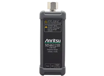
ShockLine MS46121B 1-Port USB Vector Network Analyzer, 150 kHz to 6 GHz
PC-controlled 1-port USB vector network analyzer covering 150 kHz to 6 GHz, with up to 16 units operated in parallel from one computer.
- Magnitude (150 kHz to 6 GHz)
- 0.02 dB
- Phase Noise (150 kHz to 6 GHz)
- 0.2 deg RMS
Overview
The Anritsu ShockLine MS46121B is a PC-controlled, 1-port USB vector network analyzer (VNA) with a frequency range of 150 kHz to 6 GHz. It makes 1-port S-parameter measurements and band pass time domain (distance to fault) measurements. The housing is small enough to connect directly to the device under test (DUT), so no RF cable is needed between the analyzer and the DUT.
The instrument is controlled and powered over USB from a user-supplied PC running the ShockLine software, the same graphical user interface used across the ShockLine VNA family. Up to 16 MS46121B units can be operated in parallel from one computer, with one channel per VNA. This allows parallel multisite testing of 1-port devices as an alternative to a single VNA with a switch matrix.
Options
Option 2 adds a Time Domain Reflectometry (TDR) like display that enables real impedance measurements over frequency. Option 21 Scalar Transmission enables magnitude-only transmission measurements between multiple MS46121B instruments in (1-to-1) or (1-to-n) configurations.
Secure and educational use
The MS46121B has no on-board data storage, which simplifies its use in secure areas where instruments would otherwise need data purging. It is used for passive 1-port device testing in manufacturing, engineering and university laboratories.
Key Features
- 1-port VNA with frequency options from 150 kHz to 6 GHz
- External PC control of multiple ShockLine MS46121B devices in parallel for multisite throughput
- Compact package allows direct connection to the DUT
- Scalar transmission measurements in a (1-to-1) or (1-to-n) configuration
- No on-board data storage, no data purging needed in secure applications
- Standard bandpass time domain with time gating for fault identification
- Common GUI shared across the ShockLine family
- Up to 16 MS46121B VNAs controlled from one computer
- Controlled and powered via USB from a user-supplied PC
Specifications
| Magnitude (150 kHz to 6 GHz) |
0.02 dB
Measured at 100 Hz IF bandwidth and at default power level, RMS
|
|---|---|
| Phase Noise (150 kHz to 6 GHz) |
0.2 deg RMS
Measured at 100 Hz IF bandwidth and at default power level, RMS. The Quick Fact Sheet lists 0.02 degree RMS; datasheet value used
|
| 150 kHz to 46 MHz |
–5 dBm
Default power setting, standard
|
|---|---|
| > 46 MHz to 4 GHz |
+3 dBm
Default power setting, standard
|
| > 4 GHz to 6 GHz |
–5 dBm
Default power setting, standard
|
| 150 kHz to 1 MHz |
Magnitude 0.1 dB/°C, Phase 0.1 deg/°C
Ratio measurement, with ports shorted
|
|---|---|
| > 1 MHz to 4 GHz |
Magnitude 0.01 dB/°C, Phase 0.1 deg/°C
Ratio measurement, with ports shorted
|
| > 4 GHz to 6 GHz |
Magnitude 0.05 dB/°C, Phase 0.2 deg/°C
Ratio measurement, with ports shorted
|
| Resolution |
1 Hz
Frequency resolution is 10 kHz when using an external reference
|
|---|---|
| Accuracy | ± 0.5 ppm (at time of calibration) |
| Stability | ± 1.0 ppm from - 10 °C to + 55 °C |
| Aging | ± 1.0 ppm/year |
| Directivity (150 kHz to 6 GHz) |
10 dB
User and System Correction Off. Raw directivity specification degrades by 2 dB above 4 GHz
|
|---|---|
| Port Match (150 kHz to 6 GHz) |
10 dB
User and System Correction Off. Raw port match specification degrades by 5 dB above 4 GHz
|
|
Measurement Accuracy (> 150 kHz to 4 GHz)
MS46121B-021
|
± 1.0 dB
@ 50 Hz IFBW with 10 MHz external reference, scalar normalization On, 0 dB to –50 dB insertion loss levels
|
|---|---|
|
Measurement Accuracy (> 4 GHz to 6 GHz)
MS46121B-021
|
± 2.0 dB
@ 50 Hz IFBW with 10 MHz external reference, scalar normalization On, 0 dB to –50 dB insertion loss levels
|
|
Dynamic Range (150 kHz to 6 GHz)
MS46121B-021
|
80 dB
Typical. @ 30 Hz IFBW with 10 MHz external reference, scalar normalization On, USB hub with two MS46121B instruments connected
|
|
Functional Range
MS46121B-021
|
Scalar transmission is functional to 6 GHz |
| 150 kHz to 4 GHz |
Directivity 42 dB, Source Match 35 dB, Reflection Tracking ± 0.1 dB
Calibration with TOSLN50A-8 or TOSLNF50A-8, or OSLN50A-8 and OSLNF50A-8 N-type connector manual calibration kits
|
|---|---|
| > 4 GHz to 6 GHz |
Directivity 42 dB, Source Match 35 dB, Reflection Tracking ± 0.2 dB
Calibration with TOSLN50A-8 or TOSLNF50A-8, or OSLN50A-8 and OSLNF50A-8 N-type connector manual calibration kits
|
| 150 kHz to 1 GHz |
Directivity 42 dB, Source Match 35 dB, Reflection Tracking ± 0.15 dB
MN25408A with connector options -001, -002, -003
|
|---|---|
| > 1 GHz to 5 GHz |
Directivity 40 dB, Source Match 35 dB, Reflection Tracking ± 0.2 dB
MN25408A with connector options -001, -002, -003
|
| > 5 GHz to 6 GHz |
Directivity 33 dB, Source Match 32 dB, Reflection Tracking ± 0.2 dB
MN25408A with connector options -001, -002, -003
|
| Measurement Speed |
140 µs/point, typical
100 kHz IFBW, 1601 points, 1-port calibrated; depends on external PC. Web page and Quick Fact Sheet state 120 µs/point; datasheet value used
|
|---|
|
Operating Frequencies
MS46121B-006
|
150 kHz to 6 GHz |
|---|---|
| 1-Port Measurements | S11 or any user-defined combination of a1, b1, 1 |
|
2-Port Measurements
MS46121B-021
|
S|XY| where Y is the source and X is the receiver |
| Domains | Frequency Domain and Band Pass Time Domain (Distance to Fault) |
| Frequency Sweep Types | Linear, Log, CW, or Segmented |
| Single Rectilinear Graph Types | Log Magnitude, Phase, Linear Magnitude, Real, Imaginary, SWR, and Impedance |
| Dual Rectilinear Graph Types | Log Mag and Phase, Linear Mag and Phase, Real and Imaginary |
| Circular Graph Types | Smith Chart, Polar |
| Maximum Data Points |
2 to 20,001 points
Quick Fact Sheet lists 2 to 20,000 points; datasheet value used
|
| Limit Lines | Single or segmented. 2 limit lines per trace. 50 segments per trace. |
| Ripple Value | Absolute Value or Margin |
| Averaging | Point-by-point (default) or sweep-by-sweep, maximum number of averages = 4096 |
| IF Bandwidth |
10, 20, 30, 50, 70, 100, 200, 300, 500, 700 Hz; 1, 2, 3, 5, 7, 10, 20, 30, 50, 100 kHz
All IFBW settings applicable with Option 21 enabled. Without 10 MHz external reference, IF Bandwidth can not be lower than 10 kHz
|
| Channels | Up to 16 MS46121B VNAs can operate in parallel while controlled from a single host computer; one channel per MS46121B VNA with 16 channels maximum |
|---|---|
| Traces | Each channel supports up to 16 data traces |
| Inter-trace Math | Addition, subtraction, multiplication, or division of any two traces within a channel; equation editor with over 30 built-in functions |
| Scale Resolution, Log Magnitude |
0.001 dB
Minimum per division
|
| Scale Resolution, Phase |
0.01°
Minimum per division
|
| Scale Resolution, Time |
0.0001 ps
Minimum per division
|
| Markers | 12 markers + 1 reference marker |
| Marker Statistics |
Mean, maximum, minimum, standard deviation
Per trace or over a marker region
|
| Marker Search and Tracking | Search and/or track for minimum, maximum, peak, or target value |
| Filter Parameters | Display bandwidth (user-selectable loss value), corner and center frequencies, loss, Q, and shape factors |
| S-Parameter Conversion | Z Reflection Impedance, Z Transmission Impedance, Y Reflection Admittance, Y Transmission Admittance, 1/S |
| Calibration Methods | Open Short Load (OSL), Offset Short (SSL), Triple Offset Short (SSS), SmartCal™, AutoCal™ |
|---|---|
| Correction Models | 1-Port Reflection Frequency Response (S11); 2-Port Transmission Frequency Response (Scalar) (S|XY|) |
| Dispersion Compensation | Selectable as Coaxial, other non-dispersive (e.g., for coplanar waveguide), Waveguide, or Microstrip |
| Embedding/De-embedding | Embedding/De-embedding system with multiple networks |
| Recommended Calibration Cycle |
12 months
Residual specifications also require calibration kit calibration cycle adherence
|
| CPU | Intel® Core™ i5-6300U Processor |
|---|---|
| RAM | 4 GB |
| Disk | 120 GB |
| DirectX | Version 9 with Windows Display Driver Model (WDDM) installed |
| USB |
One USB 2.0 (or higher) type A port per MS46121B used
An externally powered USB hub may also be used
|
| Operating Systems | Windows® 7, 8, 8.1, 10, or 11; 32- or 64-bit |
| Drivers | IVI-C drivers supporting National Instruments LabVIEW and LabWindows, C#, .NET, MATLAB, and Python34 |
| Test Port 1 | N(m) |
|---|---|
| Damage Input Levels | + 23 dBm maximum, ± 50 VDC maximum |
| External Reference In, Frequency |
10 MHz
Better than 10 ppm frequency accuracy is recommended
|
| External Reference In, Connector Type | MCX(f) |
| External Reference In, Signal | 0.89 Vpp, minimum; 80Ω, nominal |
| USB Ports |
One Micro USB 2.0 port for connecting to an external PC controller
For multiple MS46121B instruments on one PC, an externally powered USB 2.0 hub is recommended
|
| Dimensions (W x H x D) |
52 mm x 148 mm x 36 mm
Quick Fact Sheet lists 52 mm x 36 mm x 144 mm (HxWxD); datasheet value used
|
|---|---|
| Weight |
< 0.4 kg (< 0.9 lb)
Typical weight
|
| Environmental Class | MIL-PRF-28800F Class 2 |
|---|---|
| Operating Temperature Range |
–10 ºC to 55 ºC
Quick Fact Sheet lists 0 ºC to 50 ºC; datasheet value used
|
| Storage Temperature Range | –51 ºC to 71 ºC |
| Maximum Relative Humidity | 95 % RH at 30 ºC, non-condensing |
| Vibration, Sinusoidal | 5 Hz to 55 Hz |
| Vibration, Random | 10 Hz to 500 Hz |
| Half Sine Shock | 30 gn |
| Altitude | 4600 meters, operating and non-operating |
| European Union EMC | 2014/30/EU, EN 61326:2013, CISPR 11/EN 55011, IEC/EN 61000-4-2/3/4/5/6/8/11 |
|---|---|
| Low Voltage Directive | 2014/35/EU |
| Safety | EN 61010-1:2010 |
| RoHS | Directive 2011/65/EU & Amendment 2015/863 |
| Canada | ICES-1(A)/NMB-1(A) |
| Australia and New Zealand | RCM AS/NZS 4417:2012 |
| South Korea | R-R-A2J-1007 |
| Instrument and Built-In Options | 1 year from the date of shipment (standard warranty) |
|---|
Specifications are taken from the manufacturer's documentation. See the datasheet for complete and current values.
Applications
- Antenna return loss
- Antenna bandwidth
- Impedance measurements
- Cable fault detection
- Cable phase
- Cable return loss
- Passive 1-port device testing
- Parallel multisite testing of up to 16 DUT sites
- Scalar transmission measurements in parallel
- Secure area applications
- University laboratory education
- Production line testing
Included
- USB-A to Micro-B with latch cable, 2000-2010-R, 1.83 m (6 ft)
- Getting Started with Anritsu Flier
Options & Accessories
| Option | Description |
|---|---|
| MS46121B-006 | 150 kHz to 6 GHz, type N(m) port — Required frequency option |
| MS46121B-002 | Low Pass Time Domain — Provides a Time Domain Reflectometry (TDR) like display that enables real impedance measurements over frequency |
| MS46121B-021 | Scalar Transmission Measurement — Scalar transmission measurements between MS46121B instruments in various configurations |
| MN25208A | 2-port USB SmartCal Module, 300 kHz to 8.5 GHz — Available with connector Options -001 N(f), -002 K(f), -003 3.5 mm(f) |
| MN25408A | 4-port USB SmartCal Module, 300 kHz to 8.5 GHz — Available with connector Options -001 N(f), -002 K(f), -003 3.5 mm(f) |
| MN25218A | 2-port USB SmartCal Module, 300 kHz to 20 GHz — Available with connector Option -002 K(f). Applies to Rev 2 SmartCal Modules; MN25218A with serial numbers <1817999 operate from 1 MHz to 20 GHz |
| MN25418A | 4-port USB SmartCal Module, 300 kHz to 20 GHz — Available with connector Option -002 K(f) |
| 36585K-2M | K Connector Precision AutoCal Module, 70 kHz to 40 GHz, K(m) to K(m) |
| 36585K-2F | K Connector Precision AutoCal Module, 70 kHz to 40 GHz, K(f) to K(f) |
| 36585K-2MF | K Connector Precision AutoCal Module, 70 kHz to 40 GHz, K(m) to K(f) |
| 2000-1809-R | Serial to USB Adapter — Required for use with 36585 AutoCal module if control PC does not have a serial port |
| 3653A | N Connector Calibration Kit, Without Sliding Loads, DC to 18 GHz, 50Ω |
| OSLN50A-8 | Precision N Male Open/Short/Load Mechanical Calibration Tee, DC to 8 GHz, 50Ω |
| OSLNF50A-8 | Precision N Female Open/Short/Load Mechanical Calibration Tee, DC to 8 GHz, 50Ω |
| TOSLN50A-8 | Precision N Male Through/Open/Short/Load Mechanical Calibration Tee, DC to 8 GHz, 50Ω |
| TOSLNF50A-8 | Precision N Female Through/Open/Short/Load Mechanical Calibration Tee, DC to 8 GHz, 50 Ω |
| 1091-26-R | Adapter, SMA(m) to N(m), DC to 18 GHz, 50Ω |
| 1091-27-R | Adapter, SMA(f) to N(m), DC to 18 GHz, 50Ω |
| 1091-80-R | Adapter, SMA(m) to N(f), DC to 18 GHz, 50Ω |
| 1091-81-R | Adapter, SMA(f) to N(f), DC to 18 GHz, 50Ω |
| 71693-R | Ruggedized adapter, K(f) to N(f), DC to 18 GHz, 50Ω |
| 34NK50 | Precision Adapter, N(m) to K(m), DC to 18 GHz, 50Ω |
| 34NKF50 | Precision Adapter, N(m) to K(f), DC to 18 GHz, 50Ω |
| 34NFK50 | Precision Adapter, N(f) to K(m), DC to 18 GHz, 50Ω |
| 34NFKF50 | Precision Adapter, N(f) to K(f), DC to 18 GHz, 50Ω |
| K220B | Precision Adapter, DC to 40 GHz, K(m) to K(m), 50Ω |
| K222B | Precision Adapter, DC to 40 GHz, K(f) to K(f), 50Ω |
| K224B | Precision Adapter, DC to 40 GHz, K(m) to K(f), 50Ω |
| 15NNF50-1.0B | Test Port Cable, Flexible, Phase Stable, 1.0 m, DC to 18 GHz, N(f) to N(m), 50 Ω |
| 15NNF50-1.5B | Test Port Cable, Flexible, Phase Stable, 1.5 m, DC to 18 GHz, N(f) to N(m), 50 Ω |
| 15NN50-1.0B | Test Port Cable, Flexible, Phase Stable, 1.0 m, DC to 18 GHz, N(m) to N(m), 50 Ω |
| 15LL50-1.0A | Test Port Extension Cable, Armored, Phase Stable, 1.0 m, DC to 26.5 GHz, 3.5 mm(m) to 3.5 mm(m), 50 Ω — Web page lists DC to 20 GHz; datasheet value used |
| 15LLF50-1.0A | Test Port Extension Cable, Armored, Phase Stable, 1.0 m, DC to 26.5 GHz, 3.5 mm(m) to 3.5 mm(f), 50 Ω — Web page lists DC to 20 GHz; datasheet value used |
| 15KK50-1.0A | Test Port Extension Cable, Armored, Phase Stable, 1.0 m, DC to 26.5 GHz, K(m) to K(m), 50 Ω — Web page lists DC to 20 GHz; datasheet value used |
| 15KKF50-1.0A | Test Port Extension Cable, Armored, Phase Stable, 1.0 m, DC to 26.5 GHz, K(m) to K(f), 50 Ω — Web page lists DC to 20 GHz; datasheet value used |
| 01-200 | Calibrated Torque End Wrench, GPC-7 and Type N |
| 01-201 | Torque End Wrench, 5/16 in, 0.9 N·m (8 lbf·in) — For tightening male devices, for SMA, 3.5 mm, 2.4 mm, K, and V connectors |
| 01-203 | Torque End Wrench, 13/16 in, 0.9 N·m (8 lbf·in) — For tightening ruggedized SMA, 2.4 mm, K and V test port connectors |
| 01-204 | End Wrench, 5/16 in, Universal, Circular, Open-ended — For SMA, 3.5 mm, 2.4 mm, K, and V connectors |