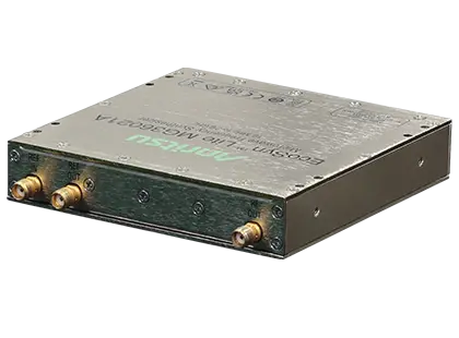
EcoSyn Lite MG36021A 10 MHz to 20 GHz Microwave Frequency Synthesizer Module
Compact 10 MHz to 20 GHz CW microwave frequency synthesizer module with low phase noise, 50 µs list-mode switching and +18 dBm output at 20 GHz.
- Frequency Range
- 10 MHz to 20 GHz
- Frequency Resolution
- 0.001 Hz
- Frequency Stability
- ± 0.3 ppm
- Frequency Accuracy
- Reference ±5 ppb
Overview
The Anritsu EcoSyn Lite MG36021A is a CW microwave frequency synthesizer module that covers 10 MHz to 20 GHz in a compact form factor. It combines low phase noise, fast frequency switching and high output power in a module intended for integration into systems and test racks.
Typical phase noise is -126 dBc/Hz at 10 GHz carrier and 10 kHz offset, and non-harmonic spurious is -60 dBc maximum. These figures allow the module to serve as a low-jitter clock source for Gbit ADC/DAC testing and in high-speed optical systems. Low phase noise at both close-in and far-out offsets, together with +18 dBm output power at 20 GHz, also suits it for use as a local oscillator for up/down converters in RF/microwave transceivers that use complex, high-order modulation.
Frequency switching time is 50 µs in triggered list mode. Fast switching reduces test time in production and ATE environments and in measurements that step through many frequencies, such as radar cross section (RCS) characterization and antenna testing.
Form factor and control
The module measures 101.6 mm x 101.6 mm x 20.32 mm (4 in x 4 in x 0.8 in), which allows use in space-constrained applications that require an instrumentation-grade CW source. It is powered from a +12 VDC supply and is controlled through USB and SPI interfaces. Standard SCPI commands and QuickSyn native commands are supported, so existing test scripts can be reused for remote control and automation.
Key Features
- 10 MHz to 20 GHz CW frequency coverage
- 0.001 Hz frequency resolution
- SSB phase noise of -126 dBc/Hz (typical) at 10 GHz and 10 kHz offset
- Non-harmonic spurious of -60 dBc (max)
- 50 µs frequency switching in triggered list mode
- +18 dBm output power at 20 GHz
- Internal 10 MHz OCXO reference plus external reference input
- Amplitude control
- Sweep and list modes
- Supports industry-standard SCPI commands for reuse of existing test scripts
- Supports QuickSyn native commands
- USB and SPI control interfaces
- Compact 4 in x 4 in x 0.8 in form factor for space-constrained applications
- Powered from a +12 VDC source
Specifications
| Frequency Range |
10 MHz to 20 GHz
Tested to 21.7 GHz
|
|---|---|
| Frequency Resolution | 0.001 Hz |
| Frequency Stability | ± 0.3 ppm |
| Frequency Accuracy | Reference ±5 ppb |
| Frequency Switching Time |
50 μs (triggered list mode)
Full band step to ±5 ppm of final frequency
|
| Frequency Switching Time (SPI) |
500 μs (individual SPI commands)
Full band step to ±5 ppm of final frequency
|
| List Mode | 64,000 points |
| Internal Reference | 10 MHz, OCXO |
|---|---|
| Output Frequency | 10 MHz nominal |
| Output Power |
+5 dBm ± 2 dBm
Web page lists Reference Output Power as 5 dBm ± 2 dB
|
| Reference Mute | –60 dBm max |
| Frequency Temp. Stability | ± 0.3 ppm |
| Aging |
± 0.5 ppm / year
Calibration command is available
|
| Locking Range | ± 2 ppm |
| Output Impedance | 50 Ω nominal |
| Input Frequency | 10 MHz |
|---|---|
| Input Power | +5 dBm ± 10 dBm |
| Absolute Max. Input Level | +15 dBm |
| Input Impedance | 50 Ω nominal |
| Output Power, 10 MHz to < 50 MHz | +15 dBm |
|---|---|
| Output Power, 50 MHz to < 3.7 GHz | +20 dBm |
| Output Power, 3.7 GHz to 20 GHz |
+18 dBm
Web page: Max Output Power +18 dBm at 20 GHz
|
| Power Control Range | > 20 dB |
| Level Accuracy | ±1.5 dB |
| Resolution | ±0.5 dB |
| RF Output On/Off Ratio | > 60 dB min, > 75 dB typical |
| Output Return Loss | 10 dB nominal |
| VSWR | 1.9 (nominal) |
| Harmonics |
–10 dBc nominal
Measured at +10 dBm
|
|---|---|
| Non-Harmonic Spurious |
–60 dBc max
Measured at +10 dBm
|
| SSB Phase Noise (headline) |
-126 dBc/Hz (typical) at 10 GHz and 10 kHz offset
Quick Fact Sheet prose states –124 dBc/Hz (typical); datasheet table gives –126 typ
|
| Phase Noise, 100 Hz offset |
0.1 GHz: –134 typ / –131 max; 1 GHz: –116 typ / –113 max; 5 GHz: –101 typ / –98 max; 10 GHz: –95 typ / –92 max; 20 GHz: –89 typ / –86 max
dBc/Hz; measured at +10 dBm
|
| Phase Noise, 1 kHz offset |
0.1 GHz: –142 typ / –139 max; 1 GHz: –137 typ / –134 max; 5 GHz: –124 typ / –121 max; 10 GHz: –118 typ / –115 max; 20 GHz: –112 typ / –109 max
dBc/Hz; measured at +10 dBm
|
| Phase Noise, 10 kHz offset |
0.1 GHz: –151 typ / –148 max; 1 GHz: –143 typ / –140 max; 5 GHz: –132 typ / –129 max; 10 GHz: –126 typ / –123 max; 20 GHz: –120 typ / –117 max
dBc/Hz; measured at +10 dBm
|
| Phase Noise, 100 kHz offset |
0.1 GHz: –156 typ / –153 max; 1 GHz: –144 typ / –141 max; 5 GHz: –134 typ / –131 max; 10 GHz: –128 typ / –125 max; 20 GHz: –121 typ / –118 max
dBc/Hz; measured at +10 dBm
|
| Phase Noise, 1 MHz offset |
0.1 GHz: –156 typ / –153 max; 1 GHz: –142 typ / –139 max; 5 GHz: –132 typ / –129 max; 10 GHz: –126 typ / –123 max; 20 GHz: –120 typ / –117 max
dBc/Hz; measured at +10 dBm
|
| Phase Noise, 10 MHz offset |
0.1 GHz: –158 typ / –155 max; 1 GHz: –151 typ / –148 max; 5 GHz: –145 typ / –142 max; 10 GHz: –139 typ / –136 max; 20 GHz: –133 typ / –130 max
dBc/Hz; measured at +10 dBm
|
| Frequency Jitter @ 100 MHz |
14.24 fs
RMS jitter, BW from 50 Hz to 15 KHz
|
| Frequency Jitter @ 1 GHz |
6.20 fs
RMS jitter, BW from 50 Hz to 15 KHz
|
| Frequency Jitter @ 5 GHz |
6.04 fs
RMS jitter, BW from 50 Hz to 15 KHz
|
| Frequency Jitter @ 10 GHz |
5.98 fs
RMS jitter, BW from 50 Hz to 15 KHz
|
| Frequency Jitter @ 20 GHz |
5.98 fs
RMS jitter, BW from 50 Hz to 15 KHz
|
| RF OUT | SMA(f) |
|---|---|
| REF OUT | SMA(f) |
| REF IN | SMA(f) |
| SPI |
14 pin, 1.27 mm spaced double-row header
Anritsu recommends Samtec manufactured mating socket assembly 07-28-G-03.25-DL-NDX series
|
| USB |
USB-C receptacle (USB 2.0)
Provides access to serial communication, used for firmware updates and remote interfaces
|
| 12 V OUT | 2 pin header. Provides power for external 12 V fan. 500 mA max. |
| Functionality | Full instrument programming control (except power on/off) |
|---|---|
| Programming Language | Standard Commands for Programmable Instruments (SCPI), QuickSyn® Native Commands |
| Interfaces | 14-pin SPI header |
| SPI Maximum Clock Frequency (FCLK) | ≤ 12 MHz |
| SPI Minimum Clock High / Low Time (TCH / TCL) | > 40 ns |
| SPI Select Low Before First Clock (TSC) | > 25 ns |
| SPI Clock Low Before Secondary Select High (TCS) | > 25 ns |
| SPI Data Stable Before Rising Clock Edge (TSU) | > 15 ns |
| Supply Voltage | +12 VDC ± 5% |
|---|---|
| Absolute Max. Supply Voltage | +15 VDC |
| Power Consumption | 15 W nominal |
| Environmental | MIL-PRF-28800F Class 2/3 |
|---|---|
| Operating Temperature |
0 ˚C to +50 ˚C (operating)
Adequate heat sinking must be provided in order to prevent permanent damage
|
| Non-operating Temperature | –40 ˚C to +70 ˚C (non-operating) |
| Warm-up Time | 30 minutes |
| European Union EMC | 2014/30/EU, EN 61326-1:2013, CISPR-11/EN 55011, IEC/EN 61000-4-2/3/4/5/6/8/11 |
|---|---|
| Low Voltage Directive | 2014/35/EU |
| Safety | EN 61010-1:2010 |
| RoHS Directive |
2011/65/EU & 2015/683
EU Declaration of Conformity lists 2011/65/EU + 2015/863
|
| Australia and New Zealand | RCM AS/NZS 4417:2012 |
| South Korea | R-R-A2J-1017 |
| Canada | ICES-1(A)/NMB-1(A) |
| Size | 101.6 mm x 101.6 mm x 20.32 mm (4 in x 4 in x 0.8 in) |
|---|---|
| Weight | 0.38 kg (0.84 lb) |
| Warranty | One-year warranty |
Specifications are taken from the manufacturer's documentation. See the datasheet for complete and current values.
Applications
- Production testing of RF/mmWave components and subsystems
- Antenna measurements
- Radar cross section (RCS) measurements
- Portable signal source for quick functional testing
- LO source for up/down converters
- Low-jitter clock source for Gbit ADC/DAC testing
- Clock source in high-speed optical systems
- CW source in RF/microwave subsystems requiring fast switching
- CW source in ATE racks
- Mil/Aero embedded solutions
Included
- 40-187-R AC/DC Power Supply, 1 m, 12 V output cable
- 2100-43-R Development Cable
- 2000-1859-R USB 3.0 Type-C to Type-A Cable, 1 m
Options & Accessories
| Option | Description |
|---|---|
| MG36021A-0098 | Standard Calibration to ISO17025 and ANSI/NCSL Z540-1, includes calibration certificate |
| 2000-2180-R | Cooling Assembly Kit — Optional accessory |