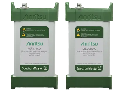
Spectrum Master MS2762A-0070 Ultraportable Spectrum Analyzer, 6 GHz to 70 GHz
USB-powered ultraportable spectrum analyzer covering 6 GHz to 70 GHz with >108 dB typical dynamic range at 70 GHz and a V (1.85 mm) test port.
- Frequency Range
- 6 GHz to 70 GHz
- Tuning Resolution
- 1 Hz
- Internal 10 MHz Frequency Reference Aging
- ±1.0 ppm/year
- Internal 10 MHz Frequency Reference Accuracy
- ±0.2 ppm (25 °C ± 25 °C) + aging
Overview
The Anritsu Spectrum Master MS2762A-0070 is an ultraportable spectrum analyzer covering 6 GHz to 70 GHz. It belongs to the MS276xA family, in which the MS2762A models offer higher dynamic range and lower displayed average noise level (DANL) than the MS2760A models, for applications with demanding sensitivity requirements.
The instrument uses Anritsu's patented nonlinear transmission line (NLTL) technology, also used in Anritsu vector network analyzers. Its pocket-sized housing allows a direct connection to the device under test, avoiding long test port cables that add loss and error at millimeter-wave frequencies. The MS2762A-0070 has a V (1.85 mm) male test port connector.
The analyzer is USB-powered and controlled from a Windows-based PC, laptop or tablet, so it can be used in the lab, on the production line or in the field. Built-in measurements include channel power, adjacent channel power and occupied bandwidth, with spectrum and spectrogram displays, up to six traces, three trace detectors and 12 markers. An external 10 MHz frequency reference input and an external TTL trigger input are provided.
Typical use cases include 5G and millimeter-wave device development, automotive radar testing, 802.11ad/WiGig spectral mask testing, satellite communications, wireless backhaul and RF component characterization in production.
Key Features
- Frequency coverage from 6 GHz to 70 GHz
- Patented NLTL technology
- Dynamic range > 108 dB typical at 70 GHz
- DANL –142 dBm typical from 6 GHz to 40 GHz
- Ultraportable form factor enables measurements right at the device under test
- USB-powered and controlled from a Windows-based PC, laptop or tablet
- Measure: channel power, adjacent channel power, occupied bandwidth
- Spectrum and spectrogram displays
- Up to 6 traces, 3 trace detectors and 12 markers
- Resolution bandwidth from 1 Hz to 3 MHz
- External 10 MHz frequency reference input
- External TTL trigger input
- V (1.85 mm) male test port connector, compatible with 2.4 mm
Specifications
| Frequency Range |
6 GHz to 70 GHz
67 GHz to 70 GHz typical
|
|---|---|
| Tuning Resolution | 1 Hz |
| Internal 10 MHz Frequency Reference Aging | ±1.0 ppm/year |
| Internal 10 MHz Frequency Reference Accuracy | ±0.2 ppm (25 °C ± 25 °C) + aging |
| Frequency Span | 10 Hz to maximum frequency range of instrument |
| Resolution Bandwidth (RBW) |
1 Hz to 3 MHz
Span ≥10 Hz; Zero Span 5 kHz to 20 MHz
|
|---|---|
| Video Bandwidth (VBW) |
1 Hz to 3 MHz
Span ≥10 Hz; Zero Span 5 kHz to 20 MHz
|
| VBW/Average Type | Linear / Log |
| RBW Filters | Flat Top, Nuttall |
| Shape Factor |
<5:1
typical
|
| Dynamic Range |
> 108 dB typical at 70 GHz
2/3 (TOI – DANL) in 1 Hz RBW
|
|---|---|
| Display Range | 1 dB to 15 dB/div in 1 dB steps, ten divisions displayed |
| Measurement Range | DANL to 0 dBm |
| Reference Level Range | –120 dBm to +30 dBm |
| Amplitude Units | dBm |
| Maximum Safe Level Input | +18 dBm CW, ±10 VDC |
| ≥ 6 GHz to 40 GHz (20 °C to 30 °C) |
±1.8 dB maximum, ±0.5 dB typical
-10 dBm CW signal, after 30 minute warm-up
|
|---|---|
| > 40 GHz to 70 GHz (20 °C to 30 °C) |
±2.0 dB maximum, ±0.5 dB typical
-10 dBm CW signal, after 30 minute warm-up
|
| ≥ 6 GHz to 40 GHz (0 °C to 50 °C) |
±3.0 dB maximum, ±1.0 dB typical
-10 dBm CW signal, after 60 minute warm-up
|
| > 40 GHz to 70 GHz (0 °C to 50 °C) |
±3.0 dB maximum, ±1.0 dB typical
-10 dBm CW signal, after 60 minute warm-up
|
| > 6 GHz to 40 GHz |
–135 dBm maximum, –142 dBm typical
RMS detection, VBW/Avg type = Log, IF Gain On, 1 Hz RBW
|
|---|---|
| > 40 GHz to 70 GHz |
–137 dBm maximum, –141 dBm typical
RMS detection, VBW/Avg type = Log, IF Gain On, 1 Hz RBW
|
| Third-Order Intercept (TOI) at 18 GHz |
+22 dBm
IF Gain Off, typical, -10 dBm tones 1 MHz apart, –10 dBm reference level
|
|---|---|
| Third-Order Intercept (TOI) at 62 GHz |
+21 dBm
IF Gain Off, typical, -10 dBm tones 1 MHz apart, –10 dBm reference level
|
| Second Harmonic Distortion |
–50 dBc maximum
–25 dBm input, at 7 GHz input
|
| 7 GHz, 1 kHz offset |
–80 dBc/Hz maximum, –89 dBc/Hz typical
20 °C to 30 °C
|
|---|---|
| 7 GHz, 10 kHz offset |
–93 dBc/Hz maximum, –97 dBc/Hz typical
20 °C to 30 °C
|
| 7 GHz, 100 kHz offset |
–94 dBc/Hz maximum, –98 dBc/Hz typical
20 °C to 30 °C
|
| 30 GHz, 1 kHz offset |
–66 dBc/Hz maximum, –74 dBc/Hz typical
20 °C to 30 °C
|
| 30 GHz, 10 kHz offset |
–81 dBc/Hz maximum, –88 dBc/Hz typical
20 °C to 30 °C
|
| 30 GHz, 100 kHz offset |
–81 dBc/Hz maximum, –88 dBc/Hz typical
20 °C to 30 °C
|
| 60 GHz, 1 kHz offset |
–60 dBc/Hz maximum, –69 dBc/Hz typical
20 °C to 30 °C
|
| 60 GHz, 10 kHz offset |
–75 dBc/Hz maximum, –84 dBc/Hz typical
20 °C to 30 °C
|
| 60 GHz, 100 kHz offset |
–75 dBc/Hz maximum, –84 dBc/Hz typical
20 °C to 30 °C
|
| Residual Spurs, 6 GHz to 70 GHz | –85 dBm maximum, –95 dBm typical |
|---|---|
| Input-related Spurious |
<–60 dBc
–20 dBm CW input
|
| Zero Span | No image rejection is applied to the sweep while in zero span, therefore spurious impact may be different. |
| 6 GHz to 12.4 GHz |
1.92:1 VSWR, 10 dB return loss
typical
|
|---|---|
| > 12.4 GHz to 50 GHz |
1.78:1 VSWR, 11 dB return loss
typical
|
| > 50 GHz to 70 GHz |
2.32:1 VSWR, 8 dB return loss
typical
|
| Source | External, Free Run, Video, Periodic (0 s to 5 s) |
|---|---|
| Delay | 0 ms to 1670 ms; –60 s (up to sweep time) in zero span and video or external trigger |
| Holdoff | 0 ms to 5000 ms |
| Slope | Rising, Falling, Both |
| Hysteresis | 0 dB to 200 dB |
| Zero Span Sweep Time | 0.02 ms to 60 s |
|---|---|
| Sweep (Trace) Points | Settable range from 10 to 10,001 points; the default is 501 points |
| Minimum Capture Time | 0 s to 10 s |
| Sweep Time Accuracy | ± 2% in Zero Span |
| Traces | Up to six traces |
| Detector Type per Trace | Peak, RMS / Avg, Negative |
| Markers | Up to 12 Markers |
| Smart Measurements | Channel Power, Occupied Bandwidth, Adjacent Channel Power |
| RF In |
V Connector (1.85 mm), male 50Ω
50 GHz and 70 GHz instruments; compatible with 2.4 mm
|
|---|---|
| USB Interface | USB 3.0, Type C Connector |
| External Reference In | MCX(f), 50Ω, 10 MHz |
| External Trigger In | MCX(f), 50Ω, TTL Levels |
| Display Resolution | 16:9 / 16:10 Aspect Ratio (>1280 x 720 / 1280 x 800) |
|---|---|
| Operating System | Windows® 7, 8.1, 10; 64-bit |
| Recommended Minimum Configuration | Quad Core i7 fourth generation or higher CPU, 16 GB RAM, 128 GB Data Storage, USB 3.0 |
| Standard |
MIL-PRF-28800F Class 3
not including Windows Tablet/Laptop/PC
|
|---|---|
| Operating Temperature Range | 0 ºC to 50 ºC |
| Storage Temperature Range | –40 ºC to 71 ºC |
| Maximum Relative Humidity | 95 % RH at 30 ºC, non-condensing |
| Vibration, Sinusoidal | 5 Hz to 55 Hz |
| Vibration, Random | 10 Hz to 500 Hz |
| Half Sine Shock | 30 g |
| Altitude | 4600 meters, operating and non-operating |
| Size |
155 mm x 84 mm x 27 mm (6.1 in x 3.3 in x 1.1 in)
not including Windows Tablet/Laptop/PC
|
|---|---|
| Weight |
255 g (9.0 oz)
not including Windows Tablet/Laptop/PC
|
| Warranty |
Standard one-year warranty
Product web page states a standard three-year warranty; datasheet value shown
|
| Calibration Cycle | Recommended calibration cycle is 12 months. |
Specifications are taken from the manufacturer's documentation. See the datasheet for complete and current values.
Applications
- Automotive radar
- Satellite communications
- Radio astronomy
- Wireless backhaul
- Antenna beam pattern testing
- 5G and mmWave device development
- 802.11ad/WiGig spectral mask testing
- On-wafer spectrum measurements
- Electronic warfare and radar
- RF component and device characterization on the production line
Included
- 2000-1859-R USB 3.0 Type C to Type A Cable, 1 m
- 2000-1605-R BNC(m) to MCX(m) Cable (qty 2)
- Certificate of Calibration and Conformance
Options & Accessories
| Option | Description |
|---|---|
| MS2762A-0070-0097 | Accredited Calibration to ISO17025 and ANSI/NCSL Z540-1 — Includes calibration certificate, test report, and uncertainty data |
| MS2762A-0070-0098 | Standard Calibration to ISO17025 and ANSI/NCSL Z540-1 — Includes calibration certificate |
| MS276xA-0070-0099 | Premium Calibration to ISO17025 and ANSI/NCSL Z540-1 — Includes calibration certificate, test report, and uncertainty data |
| 2000-1929-R | Low Noise Amplifier, 18 GHz to 42 GHz, 28 dB Gain, V(m) to V(f) — Fits models MS276xA-0050 and MS276xA-0070; noise figure 4 dB |
| 2000-1933-R | USB power bank — For use with the MS276xA Low Noise Amplifier accessory |
| 2000-1880-R | Coaxial Adapter, V (f) to N (m), DC to 18 GHz, 50 Ω |
| 2000-1881-R | Coaxial Adapter, V (f) to N (f), DC to 18 GHz, 50 Ω |
| 34VFK50A | Coaxial Adapter, DC to 43.5 GHz, V(f) to K(m), 50Ω |
| 34VFKF50A | Coaxial Adapter, DC to 43.5 GHz, V(f) to K(f), 50Ω |
| 34VV50 | Coaxial Adapter, DC to 65 GHz, V(m) to V(m), 50Ω |
| 34VVF50 | Coaxial Adapter, DC to 65 GHz, V(f) to V(m), 50Ω |
| 34VFVF50 | Coaxial Adapter, DC to 65 GHz, V(f) to V(f), 50Ω |
| 41VA-3 | Fixed Attenuator, Precision, DC to 70 GHz, 1W, 3 dB, V(m) to V(f) |
| 41VA-6 | Fixed Attenuator, Precision, DC to 70 GHz, 1W, 6 dB, V(m) to V(f) |
| 41VA-10 | Fixed Attenuator, Precision, DC to 70 GHz, 1W, 10 dB, V(m) to V(f) |
| 41VA-20 | Fixed Attenuator, Precision, DC to 70 GHz, 1W, 20 dB, V(m) to V(f) |
| 41VA-30 | Fixed Attenuator, Precision, DC to 70 GHz, 1W, 30 dB, V(m) to V(f) |
| 41VA-40 | Fixed Attenuator, Precision, DC to 70 GHz, 1W, 40 dB, V(m) to V(f) |
| 1091-456-R | Waveguide Adapter, 49.9 to 67.0 GHz, WR15 to V(f) |
| 1091-457-R | Waveguide Adapter, 39.3 to 59.7 GHz, WR19 to V(f) |
| 1091-458-R | Waveguide Adapter, 33.0 to 50.1 GHz, WR22 to V(f) |
| 1091-459-R | Waveguide Adapter, 26.4 to 40.1 GHz, WR28 to V(f) |
| 35WR15VF | Precision Waveguide Coaxial Adapter, 50 GHz to 65 GHz, WR15 to V(f) |
| 35WR19VF | Precision Waveguide Coaxial Adapter, 40 GHz to 60 GHz, WR19 to V(f) |
| 35WR22VF | Precision Waveguide Coaxial Adapter, 33 GHz to 50 GHz, WR22 to V(f) |
| 2000-1867-R | Directional Horn Antenna, 17.6 to 26.7 GHz, WR42, 25 dBi gain |
| 2000-1868-R | Directional Horn Antenna, 26.4 to 40.1 GHz, WR28, 25 dBi gain |
| 2000-1869-R | Directional Horn Antenna, 33.0 to 50.1 GHz, WR22, 25 dBi gain |
| 2000-1870-R | Directional Horn Antenna, 39.3 to 59.7 GHz, WR19, 25 dBi gain |
| 2000-1871-R | Directional Horn Antenna, 49.9 to 75.8 GHz, WR15, 25 dBi gain |
| 3670V50A-1 | Test Port Cable, DC to 70 GHz, V(f) to V(m), 30.5 cm (1 ft) |
| 3670V50A-2 | Test Port Cable, DC to 70 GHz, V(f) to V(m), 61.0 cm (2 ft) |
| 01-201 | Torque Wrench, 0.9 N·m (8 lbf·in) for K, V, SMA, 3.5 mm, 2.4 mm connectors |
| 2000-1888-R | USB 3.0 Powered Extension Cable, 10 m (32 ft) — Up to two can be used in series for a total length of 20 m |
| 2000-1918-R | 4-port 200 m USB Multimode Fiber Extender System |