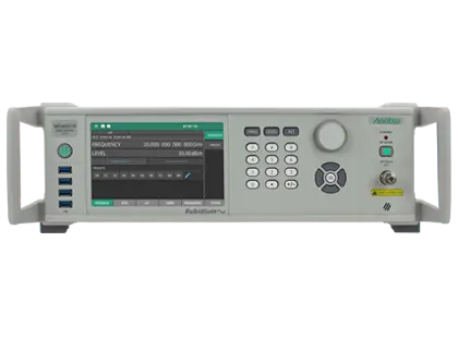
Rubidium MG36271A 9 kHz to 70 GHz RF/Microwave Signal Generator
Low-noise RF/microwave signal generator covering 9 kHz to 70 GHz with a 1.85 mm V(m) output and optional rubidium time base.
- Frequency coverage
- 9 kHz to 70 GHz
- Operable range
- Operable up to 72 GHz
- Output connector
- 1.85 mm V(m)
- Frequency resolution
- 0.001 Hz
Overview
The Anritsu Rubidium MG36271A is the 70 GHz model of the MG362x1A low-noise RF/microwave signal generator line. It covers 9 kHz to 70 GHz, can be operated up to 72 GHz, and delivers its signal through a 1.85 mm V(m) output connector.
The instrument targets applications where signal purity sets measurement quality, such as radar, transceiver, ADC/DAC and component testing. Low Phase Noise (Option 3) and Ultra Low Phase Noise (Option 13) options improve close-in and far-out phase noise respectively, and the generator also offers low harmonic and spurious levels.
Frequency stability
An internal rubidium frequency reference (Option 56) provides atomic-clock frequency stability. As an alternative, the internal oven-controlled crystal oscillator (OCXO) reference can be calibrated against an external GNSS/GPS signal using the GNSS Atomic Clock Receiver (Option 66). This makes the generator suitable for metrology and high-speed clock applications.
Modulation and pulse generation
AM, FM/PM, pulse and pulse train modulation are available, and FM and pulse modulation can run at the same time to generate waveforms such as chirps. Built-in pulse generation supports pulsed radar test, including simulation of moving targets, multiple targets and ground reflections.
Operation and connectivity
The front panel has a 7 inch touch screen, a keypad and a rotary dial. Front-panel USB ports accept memory devices and Anritsu USB power sensors. For remote control the instrument provides Ethernet and GPIB, accepts SCPI commands and ships with IVI.NET and IVI-C drivers.
Key Features
- Frequency range 9 kHz to 70 GHz, operable up to 72 GHz
- 1.85 mm V(m) RF output connector
- Low Phase Noise (Option 3) and Ultra Low Phase Noise (Option 13) options
- Atomic clock frequency stability with internal rubidium time base (Option 56)
- GNSS atomic clock receiver for on-site frequency calibration (Option 66)
- On-site user level calibration with Anritsu USB power sensors (Option 18)
- AM, FM, PM, pulse and pulse train modulation
- Simultaneous FM and pulse modulation for chirp generation
- Quad pulse signal generation and pulse sweep for radar target simulation
- High power output option (Option 15)
- Mechanical step attenuator, 90 dB (Option 2)
- 7 inch touch screen with keypad and dial
- SCPI, IVI.NET and IVI-C remote programming support
- Frequency range extendable to 1.1 THz with millimeter-wave multipliers
Specifications
| Frequency coverage | 9 kHz to 70 GHz |
|---|---|
| Operable range | Operable up to 72 GHz |
| Output connector | 1.85 mm V(m) |
| Frequency resolution | 0.001 Hz |
| Reference frequency accuracy |
1 x 10⁻⁸
When instrument leaves the factory
|
| Phase offset | Adjustable in 0.1 degree steps |
| Aging rate per year, standard (OCXO) | < ±5 × 10⁻⁷ |
|---|---|
| Aging rate per year, Option 3 (OCXO) | < ±2 × 10⁻⁸ |
| Aging rate per year, Option 56 (Rubidium) | < ±1 × 10⁻⁹ |
| Temperature effects from 0 to 55 °C, Option 56 | < ±3 × 10⁻¹⁰ |
| Short-term stability, Option 56 |
< 8 × 10–12
Allan deviation per 100 s after 2 hours warm up
|
| Reference frequency input/output |
10 MHz, 100 MHz and 1.6 GHz
100 MHz and 1600 MHz require Option 3
|
| Harmonics | -55 dBc |
|---|---|
| Harmonics, > 43.5 GHz to 70 GHz |
–55
Standard power
|
| Sub-harmonics | -63 dBc |
| Non-harmonics, > 43.5 GHz to 70 GHz |
–63
Measured at + 5 dBm for MG36271A model
|
| Residual FM at 70 GHz (Standard / Low Phase Noise / Ultra Low Phase Noise) |
6.5 Hz / 6.0 Hz / 5.0 Hz
0.05 to 15 kHz BW
|
| SSB phase noise, 10 GHz, 10 kHz offset | -136 dBc/Hz (typ) and -140 dBc/Hz (measured) |
| SSB phase noise, standard, 70 GHz, 10 kHz offset |
–109 (–114)
Typical value in parentheses
|
| SSB phase noise, Option 3, 70 GHz, 10 kHz offset |
–110 (–115)
Typical value in parentheses
|
| SSB phase noise, Option 13, 70 GHz, 10 kHz offset |
–113 (–118)
Typical value in parentheses
|
| Output power range, standard output |
–100 dBm to +6 dBm
Datasheet value (70 GHz, standard output); the web page lists -90 dBm to +6 dBm with Option 2
|
|---|---|
| Max leveled output power, 9 kHz to 13 GHz |
+18
+18 dBm with step attenuator
|
| Max leveled output power, > 13 GHz to 37 GHz |
+13.5
+11.5 dBm with step attenuator
|
| Max leveled output power, > 37 GHz to 65 GHz |
+10.5
+9.5 dBm with step attenuator
|
| Max leveled output power, > 65 GHz to 67 GHz |
+9
+5 dBm with step attenuator
|
| Max leveled output power, > 67 GHz to 70 GHz |
+6 (typical)
+3 dBm (typical) with step attenuator
|
|
Max leveled output power, High Power, 9 kHz to 2 GHz
Option 15
|
+20
+19 dBm with step attenuator
|
|
Max leveled output power, High Power, ≥ 2 GHz to 10 GHz
Option 15
|
+27
+21 dBm with step attenuator
|
|
Max leveled output power, High Power, > 10 GHz to 20 GHz
Option 15
|
+23
+21 dBm with step attenuator
|
|
Max leveled output power, High Power, > 20 GHz to 37 GHz
Option 15
|
+14.5
+11.5 dBm with step attenuator
|
|
Max leveled output power, High Power, > 37 GHz to 42 GHz
Option 15
|
+11
+8.5 dBm with step attenuator
|
|
Max leveled output power, High Power, > 42 GHz to 60 GHz
Option 15
|
+15
+11.5 dBm with step attenuator
|
|
Max leveled output power, High Power, > 60 GHz to 65 GHz
Option 15
|
+13
+9.5 dBm with step attenuator
|
|
Max leveled output power, High Power, > 65 GHz to 67 GHz
Option 15
|
+9
+5 dBm with step attenuator
|
|
Max leveled output power, High Power, > 67 GHz to 70 GHz
Option 15
|
+9 (typical)
+3 dBm (typical) with step attenuator
|
| Level accuracy and flatness | ± 2.5 dB |
| Minimum settable output power | –20 dBm without an attenuator; –130 dBm with an attenuator |
| Minimum leveled output power | –20 dBm without an attenuator; –100 dBm with an attenuator |
|
Step attenuator (Option 2)
Option 2
|
10 dB/step, 90 dB range
90 dB range on models 43.5 GHz to 70 GHz
|
| Output power resolution | 0.01 dB or 0.000 001 V |
| Output SWR (internal leveling) | < 2.0 (typical) |
| Power level stability with temperature | ± 0.04 dB/°C |
|
On-site user level calibration accuracy, to –70 dBm
Option 18
|
± 1 dB (9 kHz to 40 GHz); ± 1.5 dB (> 40 GHz to 67 GHz); ± 1.5 dB typical (> 67 GHz to 70 GHz)
Option 18
|
|
On-site user level calibration accuracy, –70 dBm to –90 dBm
Option 18
|
± 2 dB (9 kHz to 40 GHz); ± 2.5 dB (> 40 GHz to 67 GHz); ± 2.5 dB typical (> 67 GHz to 70 GHz)
Option 18
|
| Frequency sweep modes |
Step, List
Analog frequency sweep is available on MG36221A and MG36241A only
|
|---|---|
| Frequency sweep width | 9 kHz to full frequency range (step, list) |
| Power sweep |
Step, List, and Analog
Analog power sweep requires Option 16
|
| Power sweep resolution | 0.01 dB/step |
| Number of steps (phase-locked step sweep) | Variable from 2 to 65535 |
| List sweep | up to 10 tables with 4000 non-sequential frequency/power sets |
| Modulation types |
AM, FM, PM, Pulse and Pulse Train
AM/FM/PM require Option 12; pulse requires Option 26; pulse train requires Option 25
|
|---|---|
|
Pulse on/off ratio
Option 26
|
> 80 dB (70 dB for frequencies < 2 GHz)
Option 26
|
|
Minimum leveled pulse width
Option 26
|
100 ns, ≥ 2 GHz; 1 µs, < 2 GHz
Option 26
|
|
Minimum unleveled pulse width
Option 26
|
10 ns for 2 GHz to 20 GHz (external); 50 ns for > 20 GHz (external)
Option 26
|
| Pulse rise and fall time (10% to 90%), > 2 GHz | 10 ns (5 ns, (typical) |
|
Pulse modes
Option 27
|
Singlet, doublet, triplet, quadruplet
Option 27
|
| LF signal generator waveforms | Sine, square, pulse, triangle, ramp, GN/UN noise |
|
Pulse train: number of pulses per burst
Option 25
|
1 to 65535
Option 25
|
|
Pulse train: PRF range
Option 25
|
0.024 Hz to 10 MHz
Option 25
|
| Interfaces | Ethernet, GPIB (IEEE-488 interface bus) |
|---|---|
| Ethernet port | 1000 Base-T (Gbit Ethernet) |
| Commands | SCPI, Native (MG369xC compatible proprietary command set) |
| HiSLIP | Support available |
| Display | 7 inch touch screen |
|---|---|
| Power | 90 VAC to 264 VAC, 47 Hz to 63 Hz, 350 VA maximum |
| Warm up time |
From Standby: 30 minutes
From cold start (0 °C): 120 hours to achieve specified frequency stability with aging
|
| Weight | 20.5 kg |
| Dimensions (WxHxD) | 483 mm x 133 mm x 552 mm |
| Calibration cycle |
2 years
Recommended, from the date of shipment
|
| Warranty | 1 year from shipment date |
| Storage temperature range |
–40 °C to +75 °C
MIL-PRF-28800F, class 3
|
Specifications are taken from the manufacturer's documentation. See the datasheet for complete and current values.
Applications
- Avionics and aircraft manufacturing
- Radar and electronics peacekeeping
- Single tone distortion – P1dB compression point
- Two tone intermodulation – IP2, IP3
- In band and out of band interference (C/I, Blocking)
- Pulse modulated signal source for radar system testing
- Pure CW source for LO substitution in transceiver chain testing
- Clock and CW source for testing Gbit data converters (ADCs and DACs)
- Additional synchronized source for vector analyzer swept measurements
- Frequency reference for calibration and metrology labs
Options & Accessories
| Option | Description |
|---|---|
| MG362x1A-0001 | Rack Mount with Slides — Cannot be ordered with Option 11 |
| MG362x1A-0002 | Mechanical Step Attenuator, 90 dB (MG36271A) |
| MG362x1A-0003 | Low Phase Noise and High Stability — Required for Option 13 |
| MG362x1A-0010 | User Defined Modulation — Requires Option 12, Option 26, and Option 27 when ordering without Option 15. Requires Option 12, Option 27, and Option 45 when ordering with Option 15. |
| MG362x1A-0011 | Rack Mount without Slides (Shelf Mount) |
| MG362x1A-0012 | Amplitude, Frequency and Phase Modulation, Internal/External — Requires Option 27 |
| MG362x1A-0013 | Ultra Low Phase Noise — Requires Option 3 |
| MG362x1A-0015 | High Power Output — Cannot be ordered with Option 26. Choose Option 45 when ordering with Option 26 |
| MG362x1A-0016 | Analog Power Sweep |
| MG362x1A-0017 | Delete Front Panel — Requires Option 1 or 11. Cannot be ordered with Option 29 |
| MG362x1A-0018 | On-site User Level Calibration — Requires 2000-2166-R accessory kit and MA243x0A USB Power Sensor, sold separately |
| MG362x1A-0025 | Pulse Train Modulation — Always requires Option 27. Also requires Option 26, or when ordered with Option 15, requires Option 45 |
| MG362x1A-0026 | Pulse Modulation, Internal/External — Always requires Option 27. When ordered with Option 15, choose Option 45 instead of Option 26 |
| MG362x1A-0027 | Modulation Hardware — Requires at least one of Option 12 and/or Option 26, or Option 45 |
| MG362x1A-0029 | Front Panel Modulation Input/Output Access — Always requires Option 27. Requires either Option 12 and/or Option 26. When ordered with Option 15 requires Option 45 and/or Option 12. Cannot order with Option 17 |
| MG362x1A-0030 | 600 ohms External AM/FM Input Impedance — Requires Option 12 and 27 |
| MG362x1A-0033 | Phase Noise, Export Option — Cannot be ordered with Options 3, 13, or 56 for MG36241A or MG36271A |
| MG362x1A-0037 | Removable SDIO Memory |
| MG362x1A-0045 | High Power Pulse Modulation — Requires Option 27. Cannot be ordered with Option 15 or Option 17 |
| MG362x1A-0056 | Ultra Stability Time Base — Requires Option 3 or 13 |
| MG362x1A-0066 | GNSS Atomic Clock Receiver — Requires option 3 or 13 |
| MG362x1A-0097 | Accredited Calibration to ISO17025 and ANSI/NCSL Z540-1 — Includes calibration certificate, test report, and uncertainty data |
| MG362x1A-0098 | Standard Calibration to ISO17025 and ANSI/NCSL Z540-1 — Includes calibration certificate |
| MG362x1A-0099 | Premium Calibration to ISO17025 and ANSI/NCSL Z540-1 — Includes calibration certificate, test report, and uncertainty data |