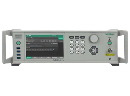
Rubidium MG36241A 9 kHz to 43.5 GHz RF/Microwave Signal Generator
Rubidium RF/microwave signal generator covering 9 kHz to 43.5 GHz with low phase noise and optional atomic clock frequency stability.
- Frequency coverage
- 9 kHz to 43.5 GHz
- Output connector
- 2.92 mm K(m)
- Frequency resolution
- 0.001 Hz
- Reference frequency accuracy
- 1 x 10⁻⁸
Overview
The Anritsu Rubidium MG36241A is the 43.5 GHz model of the MG362x1A RF/microwave signal generator family, covering 9 kHz to 43.5 GHz with a 2.92 mm K(m) output connector. It is intended for applications where signal purity matters, such as radar, transceiver, ADC/DAC and component testing.
The standard instrument specifies SSB phase noise of –136 dBc/Hz (typical) at 10 GHz output and 10 kHz offset. A Low Phase Noise option (Option 3) improves close-in phase noise and frequency stability, and an Ultra Low Phase Noise option (Option 13) improves phase noise at higher offsets.
Frequency stability
An internal rubidium frequency reference option (Option 56) provides atomic clock frequency stability. Alternatively, a GNSS/GPS atomic clock receiver (Option 66) can be used to calibrate the internal OCXO reference against satellite signals, allowing on-site frequency calibration.
Modulation and sweeps
AM, FM/PM, pulse and pulse train modulation are available as options, and simultaneous FM and pulse modulation allows generation of chirp signals. Step, list and analog frequency sweeps are supported on this model, as well as step, list and analog power sweeps.
Operation and connectivity
The front panel provides a 7-inch touch screen with keypad and rotary dial, and USB ports for memory devices and Anritsu USB power sensors. Remote control is available via Ethernet and GPIB using SCPI commands, with IVI.NET and IVI-C drivers.
Key Features
- Frequency range 9 kHz to 43.5 GHz
- SSB phase noise of –136 dBc/Hz (typical) at 10 GHz output, 10 kHz offset
- Low Phase Noise (Option 3) and Ultra Low Phase Noise (Option 13) options
- Atomic clock frequency stability with internal rubidium time base option
- GNSS atomic clock receiver option for on-site frequency calibration
- On-site user level calibration with Anritsu USB power sensors
- AM, FM, PM, pulse and pulse train modulation
- Simultaneous synchronized FM and pulse modulation for chirp generation
- Quad pulse signal generation and pulse sweep for radar target simulation
- Analog frequency sweep with up to 20 independent markers
- Analog power sweep
- High power output option
- 7-inch touch screen with keypad and rotary dial
- IVI.NET and IVI-C drivers with SCPI support
Specifications
| Frequency coverage | 9 kHz to 43.5 GHz |
|---|---|
| Output connector | 2.92 mm K(m) |
| Frequency resolution | 0.001 Hz |
| Reference frequency accuracy |
1 x 10⁻⁸
When instrument leaves the factory
|
| Phase offset | Adjustable in 0.1 degree steps |
| Reference frequency input/output | 10 MHz, 100 MHz and 1.6 GHz |
| Aging rate per year, standard (OCXO) | < ±5 × 10⁻⁷ |
|---|---|
|
Aging rate per year, Option 3 (OCXO)
MG362x1A-0003
|
< ±2 × 10⁻⁸ |
|
Aging rate per year, Option 56 (Rubidium)
MG362x1A-0056
|
< ±1 × 10⁻⁹ |
|
Short-term stability, Option 56
MG362x1A-0056
|
< 8 × 10–12
Allan deviation per 100 s after 2 hours warm up
|
| SSB phase noise |
-136 dBc/Hz (typ) and -140 dBc/Hz (measured)
@ 10 GHz output, 10 kHz offset
|
|---|---|
| Harmonics | -55 dBc |
| Sub harmonics | -83 dBc |
| Non-harmonics | -63 dBc |
| Output power range |
-130 dBm to +16 dBm
Standard output, with Option 2
|
|---|---|
| Max leveled output power, 9 kHz to 2 GHz |
+19 dBm (+18 dBm with step attenuator)
Standard power
|
| Max leveled output power, 2 GHz to 10 GHz |
+19 dBm (+18 dBm with step attenuator)
Standard power
|
| Max leveled output power, > 10 GHz to 20 GHz |
+16 dBm (+15 dBm with step attenuator)
Standard power
|
| Max leveled output power, > 20 GHz to 43.5 GHz |
+16 dBm (+15 dBm with step attenuator)
Standard power
|
|
Max leveled output power, ≥ 2 GHz to 10 GHz (Option 15)
MG362x1A-0015
|
+29 dBm (+27 dBm with step attenuator)
High power
|
|
Max leveled output power, > 10 GHz to 20 GHz (Option 15)
MG362x1A-0015
|
+23 dBm (+22 dBm with step attenuator)
High power
|
|
Max leveled output power, > 40 GHz to 43.5 GHz (Option 15)
MG362x1A-0015
|
+20 dBm (+15 dBm with step attenuator)
High power
|
| Level accuracy and flatness | ± 1.4 dB |
| Minimum leveled output power without attenuator | –15 dBm |
| Minimum leveled output power with attenuator | –120 dBm |
|
Step attenuator (Option 2)
MG362x1A-0002
|
10 dB/step, 110 dB range |
| Output power resolution | 0.01 dB or 0.000 001 V |
| Output SWR (internal leveling) | < 2.0 (typical) |
| Power level stability with temperature | ± 0.04 dB/°C |
| Modulation types | AM, FM, PM, Pulse and Pulse Train |
|---|---|
| Pulse modulation rise/fall times | 5 ns (typical) |
|
Pulse on/off ratio
MG362x1A-0026
|
> 80 dB (70 dB for frequencies < 2 GHz)
Option 26
|
|
Minimum leveled pulse width
MG362x1A-0026
|
100 ns, ≥ 2 GHz; 1 µs, < 2 GHz
Option 26
|
| LF signal generator waveforms | Sine, square, pulse, triangle, ramp, GN/UN noise |
| Frequency sweep modes |
Step, List, Analog
Analog sweep requires Option 6
|
|---|---|
| Frequency sweep width | 9 kHz to full frequency range (step, list); 100 MHz to full frequency range (analog) |
| Power sweep |
Step, List, and Analog
Analog power sweep requires Option 16
|
| Power sweep resolution | 0.01 dB/step |
| Power | 90 VAC to 264 VAC, 47 Hz to 63 Hz, 350 VA maximum |
|---|---|
| Weight | 20.5 kg |
| Dimensions (WxHxD) | 483 mm x 133 mm x 552 mm |
| Warm up time from standby | 30 minutes |
| Calibration cycle |
2 years from the date of shipment
Recommended
|
| Warranty | 1 year from shipment date |
| Storage temperature range |
–40 °C to +75 °C
MIL-PRF-28800F, class 3
|
| Interfaces | Ethernet, GPIB (IEEE-488 interface bus) |
|---|---|
| Ethernet port | 1000 Base-T (Gbit Ethernet) |
| Commands | SCPI, Native (MG369xC compatible proprietary command set) |
| HiSLIP | Support available |
Specifications are taken from the manufacturer's documentation. See the datasheet for complete and current values.
Applications
- Avionics and aircraft manufacturing
- Radar and electronics peacekeeping
- Pulsed radar system testing
- Single tone distortion and P1dB compression measurements
- Two tone intermodulation (IP2, IP3) measurements
- In-band and out-of-band interference testing
- LO substitution in transceiver testing
- Clock source for Gbit ADC and DAC testing
- Swept measurements synchronized with vector network analyzers
- Calibration and metrology labs
Options & Accessories
| Option | Description |
|---|---|
| MG362x1A-0001 | Rack Mount with Slides — Cannot be ordered with Option 11 |
| MG362x1A-0002 | Mechanical Step Attenuator, 110 dB |
| MG362x1A-0003 | Low Phase Noise and High Stability — Required for Option 13 |
| MG36241A-0006 | Analog Sweep, Frequency |
| MG362x1A-0009 | Rear Panel K(m) Connector RF Output — For MG36221A and MG36241A |
| MG362x1A-0010 | User Defined Modulation — Requires Option 12, Option 26, and Option 27 when ordering without Option 15. Requires Option 12, Option 27, and Option 45 when ordering with Option 15. |
| MG362x1A-0011 | Rack Mount without Slides (Shelf Mount) |
| MG362x1A-0012 | Amplitude, Frequency and Phase Modulation, Internal/External — Requires Option 27 |
| MG362x1A-0013 | Ultra Low Phase Noise — Requires Option 3 |
| MG362x1A-0015 | High Power Output — Cannot be ordered with Option 26. Choose Option 45 when ordering with Option 26. |
| MG362x1A-0016 | Analog Power Sweep |
| MG362x1A-0017 | Delete Front Panel — Requires Option 1 or 11. Cannot be ordered with Option 29. |
| MG362x1A-0018 | On-site User Level Calibration — Requires 2000-2166-R accessory kit and MA243x0A USB Power Sensor, sold separately |
| MG362x1A-0025 | Pulse Train Modulation — Always requires Option 27. Also requires Option 26, or when ordered with Option 15, requires Option 45. |
| MG362x1A-0026 | Pulse Modulation, Internal/External — Always requires Option 27. When ordered with Option 15, choose Option 45 instead of Option 26. |
| MG362x1A-0027 | Modulation Hardware — Requires at least one of Option 12 and/or Option 26, or Option 45 |
| MG362x1A-0029 | Front Panel Modulation Input/Output Access — Always requires Option 27. Requires either Option 12 and/or Option 26. When ordered with Option 15 requires Option 45 and/or Option 12. Cannot order with Option 17. |
| MG362x1A-0030 | 600 ohms External AM/FM Input Impedance — Requires Option 12 and 27 |
| MG362x1A-0033 | Phase Noise, Export Option — Cannot be ordered with Options 3, 13, or 56 for MG36241A |
| MG362x1A-0037 | Removable SDIO Memory |
| MG362x1A-0045 | High Power Pulse Modulation — Requires Option 27. Cannot be ordered with Option 15 or Option 17. |
| MG362x1A-0056 | Ultra Stability Time Base — Requires Option 3 or 13 |
| MG362x1A-0066 | GNSS Atomic Clock Receiver — Requires Option 3 or 13 |
| MG36241A-0082 | K(f) Connector |
| MG362x1A-0097 | Accredited Calibration to ISO17025 and ANSI/NCSL Z540-1 — Includes calibration certificate, test report, and uncertainty data |
| MG362x1A-0098 | Standard Calibration to ISO17025 and ANSI/NCSL Z540-1 — Includes calibration certificate |
| MG362x1A-0099 | Premium Calibration to ISO17025 and ANSI/NCSL Z540-1 — Includes calibration certificate, test report, and uncertainty data |