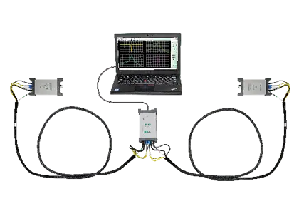
ShockLine ME7869A-043 PhaseLync Modular 2-Port Vector Network Analyzer System, 1 MHz to 43.5 GHz
Distributed 2-port ShockLine VNA system covering 1 MHz to 43.5 GHz, with PhaseLync-synchronized ports up to 100 meters apart.
- Frequency range
- 1 MHz to 43.5 GHz
- Frequency resolution
- 1 Hz
- Frequency accuracy
- ± 1.0 ppm
- Frequency stability
- ± 1.0 ppm from -10 °C to +55 °C
Overview
The ShockLine ME7869A-043 is the 43.5 GHz frequency configuration of the Anritsu ME7869A distributed modular 2-port vector network analyzer. The system consists of two ShockLine MS46131A 1-port VNAs synchronized with PhaseLync technology and the MN25132A 2-port PhaseLync control module, and covers 1 MHz to 43.5 GHz for S-parameter and time domain measurements.
The two MS46131A VNAs become the test ports and provide the source and measurement capabilities of the 2-port system. PhaseLync synchronization options MS46131A-025/050/100 support port separations of up to 100 meters, so the VNA ports can be connected directly at the device under test instead of using a benchtop VNA with long cable runs. This removes cable insertion loss from the measurement path and improves measurement stability.
The system is controlled over USB from an external PC running ShockLine software, which is shared with the rest of the ShockLine VNA family and provides a graphical user interface and a common command syntax for remote programming. Port count can be configured session by session as a single 1-port, dual 1-ports or a single 2-port VNA.
An optional time domain capability (MS46131A-002) adds low-pass and band-pass time domain with time gating, providing a TDR-like display for characterizing discontinuities. Because the units have no onboard data storage, the system is suited to secure applications.
Key Features
- 2-port VNA covering 1 MHz to 43.5 GHz
- Remote ports can be placed up to 100 meters apart with PhaseLync synchronization
- PhaseLync length options for 20, 50 and 100 meters
- Small, lightweight ports connect directly to the DUT, eliminating long cable runs
- Guaranteed performance to 43.5 GHz with Extended-K ports
- PC control uses external computer processing power and functionality
- No on-board data storage for use in secure applications
- Common ShockLine control software with debug and test capabilities
- PhaseLync control module MN25132A
- Configurable as single 1-port, dual 1-port or single 2-port VNA
- Optional low-pass time domain with time gating
Specifications
| Frequency range | 1 MHz to 43.5 GHz |
|---|---|
| Frequency resolution | 1 Hz |
| Frequency accuracy |
± 1.0 ppm
At time of calibration
|
| Frequency stability |
± 1.0 ppm from -10 °C to +55 °C
Typical
|
| Aging |
± 1.0 ppm/year
Typical
|
| 1 MHz to 5 GHz |
97 dB (110 typical)
High source power minus RMS noise floor at 10 Hz IF bandwidth, high isolation mode
|
|---|---|
| > 5 GHz to 8.5 GHz |
97 dB (105 typical)
May degrade in > 5 GHz to 7 GHz range to 90 dB (105 dB typical); may be degraded on -020 and -043 options due to receiver residuals: 91 dB (97 dB typical)
|
| > 8.5 GHz to 20 GHz | 98 dB (110 typical) |
| > 20 GHz to 40 GHz | 102 dB (110 typical) |
| > 40 GHz to 43.5 GHz | 99 dB (110 typical) |
| 1 MHz to 6 GHz |
0.009 dB (0.003 typical); 0.12 deg (0.03 typical)
100 Hz IF bandwidth, High power level, RMS
|
|---|---|
| > 6 GHz to 8 GHz | 0.022 dB (0.01 typical); 0.15 deg (0.08 typical) |
| > 8 GHz to 40 GHz | 0.006 dB (0.001 typical); 0.1 deg (0.02 typical) |
| > 40 GHz to 43.5 GHz | 0.009 dB (0.002 typical); 0.12 deg (0.03 typical) |
| 1 MHz to 4 GHz |
0.007 dB (0.0015 typical); 0.21 deg (0.02 typical)
100 Hz IF bandwidth, High power level, RMS exclusive of drift, High Isolation Mode off
|
|---|---|
| > 4 GHz to 8 GHz | 0.011 dB (0.003 typical); 0.51 deg (0.08 typical) |
| > 8 GHz to 20 GHz |
0.006 dB (0.0015 typical); 0.51 deg (0.08 typical)
Phase noise degraded to 0.6 deg (0.41 typical) for MS46131A-100
|
| > 20 GHz to 43.5 GHz |
0.011 dB (0.0025 typical); 0.59 deg (0.25 typical)
Phase noise degraded to 1.6 deg (0.56 typical) for MS46131A-100
|
| Receiver compression level, 1 MHz to 43.5 GHz |
+ 5 dBm
Port power beyond which response may be compressed more than 0.1 dB; typical
|
|---|---|
| Output power, High (default) |
0 dBm ±2dB
Typical
|
| Output power, Low |
– 20 dBm ±2dB
Typical
|
| Output power, Off |
-50 dBm
Typical
|
| 1-port, 1 MHz to 43.5 GHz |
0.02 dB/ºC; 0.3 deg/ºC
Typical
|
|---|---|
| 2-port, 1 MHz to 8 GHz |
0.015 dB/ºC; 0.4 deg/ºC
Typical; ratioed transmission, short thru, 20 m PhaseLync interconnect (values approximately scale with length)
|
| 2-port, > 8 GHz to 20 GHz |
0.015 dB/ºC; 0.5 deg/ºC
Typical; 20 m PhaseLync interconnect
|
| 2-port, > 20 GHz to 43.5 GHz |
0.02 dB/ºC; 1.25 deg/ºC
Typical; for PhaseLync configurations of 50 m or more above 20 GHz, phase stability is approximately 2 degrees per °C
|
| 50 kHz to 1 GHz |
Directivity > 21 dB; Port match > 17 dB
Typical; user correction off, system correction on; port match is worst of source and load match
|
|---|---|
| > 1 GHz to 4 GHz |
Directivity > 21 dB; Port match > 17 dB
Typical
|
| > 4 GHz to 8.5 GHz |
Directivity > 15 dB; Port match > 15 dB
Typical
|
| > 8.5 GHz to 43.5 GHz |
Directivity > 15 dB; Port match > 15 dB
Typical
|
| 1 MHz to 10 GHz |
Directivity 42 dB; Source match 33 dB; Load match 41 dB; Reflection tracking ± 0.15 dB; Transmission tracking ±0.06 dB
Load match and tracking are characteristic performance
|
|---|---|
| > 10 GHz to 20 GHz | Directivity 36 dB; Source match 26 dB; Load match 35 dB; Reflection tracking ± 0.15 dB; Transmission tracking ±0.06 dB |
| > 20 GHz to 30 GHz | Directivity 32 dB; Source match 22 dB; Load match 31 dB; Reflection tracking ± 0.15 dB; Transmission tracking ±0.06 dB |
| > 30 GHz to 40 GHz | Directivity 30 dB; Source match 20 dB; Load match 29 dB; Reflection tracking ± 0.15 dB; Transmission tracking ±0.06 dB |
| > 40 GHz to 43.5 GHz |
Directivity 28 dB; Source match 20 dB; Load match 27 dB; Reflection tracking ± 0.2 dB; Transmission tracking ±0.16 dB
For 100 m systems, transmission phase uncertainty is 2.5 degrees at 40 GHz and 3 degrees at 43.5 GHz (device transmission -65 dB to +5 dB)
|
| 1 MHz to 50 MHz |
Directivity 45 dB; Source match 45 dB; Load match 44 dB; Reflection tracking ± 0.15 dB; Transmission tracking ±0.06 dB
Load match and tracking are characteristic performance
|
|---|---|
| > 0.05 GHz to 10 GHz | Directivity 45 dB; Source match 45 dB; Load match 44 dB; Reflection tracking ± 0.15 dB; Transmission tracking ±0.06 dB |
| > 10 GHz to 20 GHz | Directivity 45 dB; Source match 45 dB; Load match 44 dB; Reflection tracking ± 0.15 dB; Transmission tracking ±0.06 dB |
| > 20 GHz to 30 GHz | Directivity 45 dB; Source match 44 dB; Load match 44 dB; Reflection tracking ± 0.15 dB; Transmission tracking ±0.06 dB |
| > 30 GHz to 40 GHz | Directivity 45 dB; Source match 42 dB; Load match 44 dB; Reflection tracking ± 0.15 dB; Transmission tracking ±0.06 dB |
| > 40 GHz to 43.5 GHz | Directivity 42 dB; Source match 41 dB; Load match 41 dB; Reflection tracking ± 0.2 dB; Transmission tracking ±0.16 dB |
| Sweep speed | 170 µs/point typical |
|---|---|
| Maximum dynamic range |
100 dB maximum
Datasheet lists 97 dB to 102 dB specified (110 dB typical) depending on band
|
Specifications are taken from the manufacturer's documentation. See the datasheet for complete and current values.
Applications
- Long cable insertion loss testing
- Antenna testing
- Over the Air (OTA) applications
- Chamber installations
- Large vehicle RF shielding and propagation testing
- System calibration
- Path-loss characterization
- General S-parameter and time domain measurements
- Secure area applications
Included
- Two MS46131A modular 1-port VNAs
- MN25132A PhaseLync control module
Options & Accessories
| Option | Description |
|---|---|
| MN25132A | PhaseLync 2-port control module |
| MS46131A-025 | Option 25, PhaseLync synchronization to 20 meters — Order one for each MS46131A VNA |
| MS46131A-050 | Option 50, PhaseLync synchronization to 50 meters — Order one for each MS46131A VNA |
| MS46131A-100 | Option 100, PhaseLync synchronization to 100 meters — Order one for each MS46131A VNA |
| 2000-2123-R | PhaseLync 2 meter cable set — Two cable sets required; total length must be within the PhaseLync length option |
| 2000-2124-R | PhaseLync 5 meter cable set |
| 2000-2125-R | PhaseLync 10 meter cable set |
| 2000-2126-R | PhaseLync 25 meter cable set |
| 2000-2127-R | PhaseLync 50 meter cable set |
| 2000-2128-R | PhaseLync 75 meter cable set |
| MS46131A-002 | Time Domain with Time Gating — Required on each MS46131A for time domain to be enabled on the 2-port VNA |
| 760-299-R | Transit case for the ME7869A VNA system |
| 36585K-2M | K Precision AutoCal Module, 70 kHz to 40 GHz, K(m) to K(m) |
| 36585K-2F | K Precision AutoCal Module, 70 kHz to 40 GHz, K(f) to K(f) |
| 36585K-2MF | K Precision AutoCal Module, 70 kHz to 40 GHz, K(m) to K(f) |
| TOSLK50A-43.5 | Precision K Male Through/Open/Short/Load Mechanical Calibration Tee with S1P data, DC to 43.5 GHz, 50 Ω |
| TOSLKF50A-43.5 | Precision K Female Through/Open/Short/Load Mechanical Calibration Tee with S1P data, DC to 43.5 GHz, 50 Ω |
| 3668-4 | 43.5 GHz K Connector Verification Kit |
| 3670K50A-1 | Test Port Cable, Armored, Semi-rigid, 30.48 cm (1 ft), DC to 43.5 GHz, K(m) to K(f), 50 Ω |
| 3670K50A-2 | Test Port Cable, Armored, Semi-rigid, 60.96 cm (2 ft), DC to 43.5 GHz, K(m) to K(f), 50 Ω |
| 806-425-R | Flexible Phase Stable Cable, DC to 43.5 GHz, 1 m (39.4 in), K(f) – K(f), 50 Ω |
| 806-426-R | Flexible Phase Stable Cable, DC to 43.5 GHz, 1 m (39.4 in), K(m) – K(f), 50 Ω |
| 33KKF50C | Calibration Grade Adapter, K(m) to K(f), DC to 43.5 GHz, 50 Ω |
| 01-201 | Torque End Wrench, 5/16 in, 0.9 N.m (8 lbf·in) — For tightening male SMA, 3.5 mm, 2.4 mm, K and V connectors |