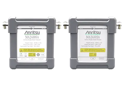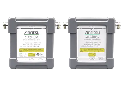
Anritsu MA24105A Inline Peak Power Sensor, True-RMS, 350 MHz to 4 GHz
True-RMS inline peak power sensor measuring forward and reverse power from 2 mW to 150 W over 350 MHz to 4 GHz.
- Frequency Range
- 350 MHz to 4 GHz
- Measurement Range
- 2 mW to 150 W (+3 dBm to +51.76 dBm)
- Input Return Loss
- ≥ 29.5 dB from 350 MHz to 3 GHz; ≥ 26.5 dB from > 3 GHz to 4 GHz
- Insertion Loss
- ≤ 0.15 dB from 350 MHz to 1.25 GHz; ≤ 0.20 dB from > 1.25 GHz to 4 GHz
Overview
The Anritsu MA24105A Inline Peak Power Sensor takes average power measurements from 2 mW to 150 W over a frequency range of 350 MHz to 4 GHz. It measures CW, multi-tone and digitally modulated signals such as GSM/EDGE, CDMA/EV-DO, W-CDMA/HSPA+, WiMAX and TD-SCDMA. The MA24105A belongs to the MA2410xA inline sensor family, alongside the MA24103A, which covers 25 MHz to 1 GHz.
Measurement architecture
A "dual path" architecture gives True-RMS measurements across the full frequency and dynamic range. The forward direction path includes a 4 MHz bandwidth channel with peak and comparator/integrator circuits, which add peak envelope power (PEP), crest factor, complementary cumulative distribution function (CCDF) and burst average power measurements. A detection circuit in the reverse direction adds reverse power, reflection coefficient, return loss and SWR measurements. Because the sensor contains a micro-controller, signal conditioning circuitry, an ADC and a power supply, it works as a complete miniature power meter.
Operation with a PC
The sensor connects over USB to a PC running Microsoft Windows (including Windows 11) and is used with the Anritsu PowerXpert application for data display, analysis and sensor control. PowerXpert provides data logging, power versus time graphs, a single sensor display, real-time settings updates and offset tables.
Operation with Anritsu handheld instruments
Anritsu handheld instruments that have the high accuracy power meter software Option 19 can operate the sensor through a USB A/Micro-B cable. The MA2410xA sensors work with most Anritsu handheld instruments; the instrument's technical data sheet confirms compatibility.
Key Features
- True-RMS average power measurements to 150 W
- Covers cellular and communication bands such as WLL, GSM/EDGE, CDMA/EV-DO, W-CDMA/HSPA+, WiMAX and TD-SCDMA
- Forward and reverse measurements of transmitted power and reflections with a single inline sensor
- Forward peak measurements: PEP, crest factor, CCDF and burst average power
- Reverse measurements: reverse power, reflection coefficient, return loss and SWR
- Wide dynamic range of 2 mW to 150 W (+3 dBm to +51.76 dBm)
- Suited to high crest factor signals and base station transmitter output power measurements
- High power handling > +51.7 dBm
- Plug and play USB device operated from a PC with PowerXpert software v3.49 or later
- Compatible with Anritsu handheld instruments with high accuracy power meter Option 19
Specifications
| Frequency Range | 350 MHz to 4 GHz |
|---|---|
| Measurement Range | 2 mW to 150 W (+3 dBm to +51.76 dBm) |
| Input Return Loss |
≥ 29.5 dB from 350 MHz to 3 GHz; ≥ 26.5 dB from > 3 GHz to 4 GHz
Web page lists >29.5 dB, ≤ 3 GHz and >26.5 dB, ≤ 4 GHz
|
| Insertion Loss |
≤ 0.15 dB from 350 MHz to 1.25 GHz; ≤ 0.20 dB from > 1.25 GHz to 4 GHz
typical
|
| Directivity |
≥ 28 dB from 350 MHz to < 1 GHz; ≥ 30 dB from ≥ 1 GHz to ≤ 3 GHz; ≥ 28 dB from > 3 GHz to 4 GHz
typical
|
| RF Connectors | N (F) |
| Signal Channel Bandwidth | Average 100 Hz; Peak (Selectable) 4 MHz (Full), 200 kHz, 4 kHz |
|---|---|
| Measurement Range | Range 1: 2 mW to 6.31 W (+3 dBm to +38 dBm); Range 2: 6.31 W to 150 W (+38 dBm to +51.76 dBm) |
| Maximum Power |
150 W average
Maximum power depends upon the system SWR and frequency of operation
|
| Measurement Uncertainty |
±3.8% (Range 1 and Range 2)
Expanded uncertainty with K=2 for power measurements of a CW signal with a matched load; results referenced to the input side of the sensor
|
| Effect of Noise |
±170 μW (Range 1); ±1.9 mW (Range 2)
Expanded uncertainty with K=2 after zero operation, measured with 128 averages for 5 minutes
|
| Effect of Zero Set |
±250 μW (Range 1); ±3.0 mW (Range 2)
One-hour warm up with no operation, measured with 128 averages for one hour keeping temperature within ±1 ºC
|
| Effect of Zero Drift |
±230 μW (Range 1); ±2.7 mW (Range 2)
One-hour warm up with no operation, measured with 128 averages for one hour keeping temperature within ±1 ºC
|
| Effect of Temperature (0 ºC to 50 ºC) | ±0.06 dB |
| Effect of Digital Modulation | ±0.02 dB |
| Measurement Range, Burst Signal | 2 W to 300 W (+33 dBm to +54.77 dBm) |
|---|---|
| Measurement Base Uncertainty, Full Bandwidth |
±(Base Average Power Uncertainty +7% +400 mW)
Repetition Rate ≥10/s, Duty Cycle ≥10%; Pulse Power > +34 dBm, Pulse Width > 1µs (Full BW)
|
| Measurement Base Uncertainty, 4 kHz and 200 kHz Bandwidth |
±(Base Average Power Uncertainty +3% +200 mW)
Repetition Rate ≥10/s, Duty Cycle ≥10%; Pulse Power > +34 dBm, Pulse Width > 5µs (200 kHz BW), Pulse Width > 200 µs (4 kHz BW)
|
| Effect of Low Repetition Rate |
±1.6% ±150 mW
≤ 10/s
|
| Effect of Low Duty Cycle |
±100 mW
0.1% to 10%
|
| Effect of Short Burst Width | ±5% (500 ns to 1 μs); ±10% (200 ns to < 500 ns) |
| Effect of Temperature on Peak Circuit |
±6% (0 ºC to 50 ºC)
All measurement error effects should be RSSed before being added to the base error for overall measurement uncertainty
|
| Measurement Range | 2 mW to 150 W (+3 dBm to +51.76 dBm) |
|---|---|
| Maximum Power |
150 W average
Maximum power depends upon the system SWR and frequency of operation
|
| Measurement Uncertainty |
±(Base Average Power Uncertainty)
Expanded uncertainty with K=2 for power measurements of a CW signal with a matched load
|
| Spread-spectrum Measurement Uncertainty | ±(Base Average Power Uncertainty +15% +400 mW) |
| Measurement Uncertainty |
±0.2%
Pulse Power > +37 dBm, T > 50 μs (Full BW), T > 400 μs (200 kHz BW), T > 20 ms (4 kHz BW)
|
|---|---|
| Threshold Range |
2 mW to 300 mW (+3 dBm to +54.77 dBm)
As printed; +54.77 dBm corresponds to 300 W
|
| Accuracy of Threshold | ±(Base Average Power Uncertainty at +5% +500 mW) |
| Measurement Uncertainty (User Mode) | Same as Base Average Power Uncertainty except Zero Set, Zero Drift and Noise are divided by duty cycle (t/T) |
|---|---|
| Measurement Uncertainty (Auto Mode) |
±(Base Average Power Uncertainty except Zero Set, Zero Drift and Noise are divided by duty cycle (t/T) ±2%)
Average Power > +33 dBm, Pulse width > 5 μs (Full BW), Pulse Width > 40 μs (200 kHz BW), Pulse Width > 2 ms (4 kHz BW)
|
| Reflection Measurement Uncertainty | ±(Base Average Power Uncertainty + Reverse Power Measurement Uncertainty) |
|---|---|
| Crest Factor Uncertainty | ±(Base Average Power Uncertainty + Forward Peak Power Measurement Uncertainty) |
| Measurement Resolution | 0.01 dB (Forward/Reverse True-RMS Average Power, Peak Power, Crest Factor, Burst Average Power); 0.01% (CCDF) |
|---|---|
| Offset Range | 100 dB (Forward/Reverse True-RMS Average Power, Peak Power, Crest Factor, Burst Average Power); 100% (CCDF) |
| Averaging Range |
1 to 512
All measurement types
|
| Measurement Speed |
1.7 /s (Forward/Reverse True-RMS Average Power), 2.5 /s (Peak Power), 1.4 /s (Crest Factor), 0.7 /s (Burst Average Power), 1.6 /s (CCDF)
typical; rate at which the measurement or calculation is updated in a data log
|
| USB | 180 mA typical at 5 V |
|---|---|
| Size (H x W x D) |
108 mm x 97 mm x 36 mm
excluding N Connectors
|
| Weight | 535 g (1.18 lb) |
| Calibration Cycle |
2 years
Recommended
|
| Warm-Up Time |
20 minutes
Specifications apply after warm-up with the sensor left in the on state
|
| Operating Temperature |
0 °C to 50 °C
Tests performed per MIL-PRF-28800F (Class 2)
|
|---|---|
| Storage Temperature | –51 °C to 71 °C |
| Maximum Relative Humidity |
45% relative humidity at 55 ºC; 75% relative humidity at 40 ºC; 95% relative humidity at 30 ºC
non-condensing
|
| Mechanical Shock | 30 g half-sine, 11 ms duration |
| Vibration | Sinusoidal: 5 to 55 Hz, 3 g max; Random: 10 Hz to 500 Hz, Power Spectral Density: 0.03 g²/Hz |
| European Union EMC | 2014/30/EU, EN 61326-1:2013, CISPR 11/EN 55011, IEC/EN 61000-4-2/3/4/5/6/8/11 |
|---|---|
| Low Voltage Directive | 2014/35/EU |
| Safety | EN 61010-1:2010 |
| RoHS Directive | 2011/65/EU & 2015/863 |
| United Kingdom | EMC SI 2016/1091; BS EN 55011 & BS 61000-4-2/3/4/5/6/8/11; Consumer Protection (Safety) SI 2016/1101; BS EN 61010-1:2010; Environmental Protection SI 2012/3032; 2011/65/EU & 2015/863 |
| Australia and New Zealand | RCM AS/NZS 4417:2012 |
| South Korea | R-R-A2J-1014 |
| Canada | ICES-1(A)/NMB-1(A) |
| Warranty | 1 Year Warranty |
| MA24105A |
300 MHz to 4 GHz Inline Peak Power Sensor
Ordering table states 300 MHz; specifications and web page give 350 MHz to 4 GHz
|
|---|
Specifications are taken from the manufacturer's documentation. See the datasheet for complete and current values.
Applications
- Cellular base station transmitter power monitoring
- Broadcast networks and LMR systems
- Antenna reflection measurement
- Avionics and airport navigation systems
- Railroad braking system monitoring
- Testing high power devices such as power amplifiers
- General purpose measurement of through and reflected power
- R&D and manufacturing test
Included
- 2000-1606-R 1.8 m USB 2.0 A to Micro-B cable
Options & Accessories
| Option | Description |
|---|---|
| MA24105A-0098 | Option 98, Standard calibration to ISO17025 and ANSI/NCSL Z540 |
| MA24105A-0099 | Option 99, Premium calibration to ISO17025 and ANSI/NCSL Z540 — Test report and uncertainty data included. |
| 510-90 | Precision coaxial adapter, N(m) to 7/16 DIN(f), DC to 3.3 GHz |
| 510-91 | Precision coaxial adapter, N(f) to 7/16 DIN(f), DC to 3.3 GHz |
| 510-92 | Precision coaxial adapter, N(m) to 7/16 DIN(m), DC to 3.3 GHz |
| 510-93 | Precision coaxial adapter, N(f) to 7/16 DIN(m), DC to 3.3 GHz |
| 34ANF50 | Precision coaxial adapter, GPC-7 to N(f), DC to 18 GHz |
| 34NFK50 | Precision coaxial adapter, N(f) to K(m), DC to 18 GHz |
| 34NFKF50 | Precision coaxial adapter, N(f) to K(f), DC to 18 GHz |
| 34NK50 | Precision coaxial adapter, N(m) to K(m), DC to 18 GHz |
| 34NFNF50 | Precision coaxial adapter, N(m) to N(m), DC to 18 GHz |
| 34NKF50 | Precision coaxial adapter, N(m) to K(f), DC to 18 GHz |
| 34AN50 | Precision coaxial adapter, GPC-7 to N(m), DC to 18 GHz |
| 34NN50A | Precision coaxial adapter, DC to 18 GHz, 50 Ω, N(m)-N(m) |
| 1010-121-R | Attenuator, 40 dB, 100 W, D to 18 GHz, N(f) to N(m), Uni-directional |
| 42N50-20 | Attenuator, 20 dB, 5 W, DC to 18 GHz, N(m) to N(f) |
| 3-1010-122 | Attenuator, 20 dB, 5 W, DC to 12.4 GHz, N(m) to N(f) |
| 42N50A-30 | Attenuator, 30 dB, 50 W, DC to 18 GHz, N(m) to N(f) |
| 3-1010-123 | Attenuator, 30 dB, 50 W, DC to 8.5 GHz, N(m) to N(f) |
| 1010-127-R | Attenuator, 30 dB, 150 W, DC to 3 GHz, N(m) to N(f) |
| 3-1010-124 | Attenuator, 40 dB, 100 W, DC to 8.5 GHz, N(f) to N(m), Uni-directional |
| 1010-128-R | Attenuator, 40 dB, 150 W, DC to 3 GHz, N(m) to N(f) |
| 01-200 | Calibrated Torque End Wrench, GPC-7 and Type N |
| 2000-1594-R | 5 meters USB A to Mini-B cable |
| 2000-1593-R | 3 meters USB A to Mini-B cable |
| 28N50-3 | Precision termination, DC to 8.6 GHz, 50 Ω, N male |
| 28NF50-2 | Precision termination, DC to 18 GHz, 40 dB, 50 Ω, N female |
| 28N50-2 | Precision termination, DC to 18 GHz, 40 dB, 50 Ω, N male |